

For full warranty information, refer to the AMX Instruction Manual(s) associated with your Product(s).
11/07
©2007 AMX. All rights reserved. AMX and the AMX logo are registered trademarks of AMX.
AMX reserves the right to alter specifications without notice at any time.
3000 RESEARCH DRIVE, RICHARDSON, TX 75082 • 800.222.0193 • fax 469.624.7153 • technical support 800.932.6993 • www.amx.com
93-070-604
REV: G
Step 3: Modify the Source Code on your Master
Before you can use either the Computer Control or TakeNote applications, you
must first modify the NetLinx Master Source Code to support the new (G4CC)
functionality:
1.
Insert the NXA-USBTN stick into a USB port on the PC that is being
controlled. Confirm that a new USB detection icon ( ) appears in the
windows taskbar.
2.
Launch NetLinx Studio, select
File
>
Open
, navigate to the assigned USB
stick drive and open the
cc-GuestPC Test.axs
file. This file acts as a
source for the various communication parameters needed by the Master
to allow the initial communication between the panel and the PC.
3.
Scroll through the code in the
cc-GuestPC TEST.axs
file, and add the fol-
lowing information into your Master Source Code:
• Add a Telnet device connection to your device definitions by copying the
following information from the
DEFINE_DEVICE
section (of the
cc-GuestPC TEST.axs
file) and pasting it into your source code:
vdvGuestPC = 0:5:0
• Add the entire Module Definition:
DEFINE_MODULE 'cc-GuestPCMod' <myModuleName>
(<guestPcDevice>)
where:
<myModuleName>
- local name for this instance of the cc-GuestPC
module
<guestPcDevice>
- device for cc-GuestPC to use for internal data
events; this should be a DEFINE_DEVICE for the events to work properly
4.
Save and close the
cc-GuestPC Test.axs
file.
5.
Right-click the
Module
folder (in the Workspace containing your
current Project), and select
Add Existing Module File
.
6.
Navigate to the Module folder on the USB stick, and select
*.tko
from the
Files of type
field.
7.
Select the
cc-GuestPC.tko
file and click
Open
>
OK
. This file needs to
be added to your Workspace and compiled with the source code.
8.
Save your Workspace, verify that your source code is designated as the
Master source code file, and then press
F7
to begin compiling your
Master Source Code and Module file. This process creates the .
tkn
file
that is transferred to the Master.
9.
Verify that your Master is online and communicating and select
Tools
>
File Transfer
to open the
File Transfer
dialog. Click the
Add
button
to
open the Select Files for File Transfer dialog, open to the
Current
Workspace
tab.
10. Locate the compiled
*.tkn
file and select it for transfer. Click
OK
to return
to the File Transfer dialog.
11. Click
Send
to transfer the selected
tkn
file to the target Master.
Step 4: Configure Computer Control
configCC.exe
(included on the USB stick) is the Configuration Utility for
G4CC. Use this application to designate up to four Modero or TPI/4 panels that
will be allowed to control this computer.
1.
Use the computer’s file browser to navigate to the assigned USB stick
drive location and open the
Computer Control > Config
folder.
2.
Use the
configCC.exe
application (on the USB stick) to configure the
G4CC application. Double-click the
configCC.exe
to run the
configuration utility.
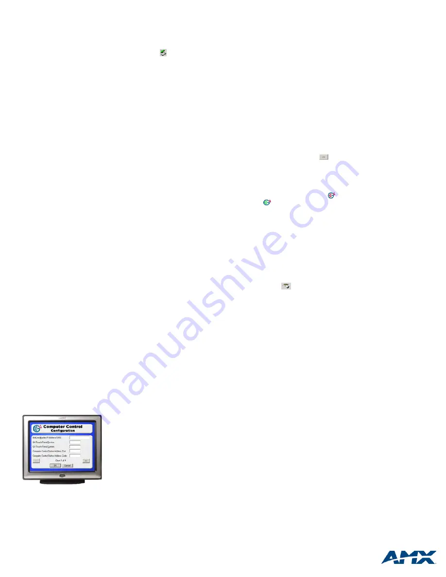
The following information is needed by the Computer Control
Configuration Utility (FIG. 3) for each G4 panel or TPI/4 interface:
•
NetLinx Master IP Address/DNS
(
Fixed IP/URL
):____.____.____.____
(Acquire the IP Address of the Master via NetLinx Studio:
select Diagnostics > Network Addresses > Get IP Information).
•
G4 Touch Panel Device ID
: _______
(Acquire the panel device number in the online tree of NetLinx
Studio).
•
G4 Touch Panel System
: _______
(Acquire the system number in the online tree of NetLinx Studio).
•
Computer Control Button Address Port
: _______
(Acquire this number via TPD4, in the Programming Tab of the Button
Properties window).
•
Computer Control Button Address Code (Channel)
: _______
(Acquire this number via TPD4, in the Programming Tab of the Button
Properties window). This information was previously entered into the
Address Code field for the Computer Control button.
3.
Press the
OK
button when finished adding a single panel. This action
modifies the
amxCC.cfg
file and stores your settings until the values
within the
configCC.exe
file are altered. Once the USB Control Stick has
been configured, it can be used on any computer residing on the Ethernet
Network that can communicate with the NetLinx Control System.
4.
Add multiple panels using the next ( ) button on the configuration
utility screen (
maximum of four panels
).
Step 5: Run the Computer Control Application
1.
Once the configuration file has been created, double-click the
amxCC.exe
file, located in the Computer Control folder, to begin your
G4CC session and display the G4CC ( ) icon in the taskbar. The icon
turns green ( ) when a Modero or TPI/4 panel is connected to the com-
puter.
2.
Upon opening this file, your PC will be displayed on the touch panel.
3.
To terminate your Computer Control session, right-click on the G4CC icon
and select
Close Computer Control
from the menu.
Step 6: Run the TakeNote Application
If you are not using a direct RGB connection (such as on a TPI/4), G4CC must
be running in order for TakeNote to function. Use the following steps to setup
and implement TakeNote:
1.
Use the computer’s file browser to navigate to the USB stick drive and
double-click the
TakeNote
executable to run the application.
2.
The TakeNote icon ( ) appears in the taskbar.
• Double-click this icon to open the TakeNote Configuration page.
• Right-mouse click opens the TakeNote Context menu. Refer to the
TakeNote Help file (F1) for more detailed information.
While you can have between 1 and 4 masters/panels connected to the PC you
should not connect more than one PC to any one master/panel.
Warranty Exception
AMX Corporation warrants this product to be free of defects in material and
workmanship under normal use for 30 days from the date of purchase from
AMX Corporation. This product is not eligible for credit return.
FIG. 3
G4 Computer Control Configuration screen
Config CC application -
PC


