Page 2
Page 7
Establishing Connection
Before using your N1512 unit, it must be configured using the free N-Able device management software. However, you will not be able to
configure units until they are in the same subnet as the host computer. N-Series devices are shipped in
DHCP
mode and the IP address will
be assigned automatically based on the network DHCP server. If no DHCP server is found, the unit will use
Auto
IP
mode with a default IP
address of 169.254.xxx.xxx.
The sample steps below show how the required changes to the host computer’s IP settings are made in a Windows environment.
Steps for IP address configuration:
1. From the
Control Panel > Network and Internet
dialog box, select
Network and Sharing Center
.
2. Select
Change adapter settings
.
3. Select the wired interface connected to your AV network.
4. Click the
Properties
button.
5. Scroll down in the list to the
Internet Protocol Version 4 (TCP/IPv4)
option. Highlight it and click the
Properties
button.
6. Enable the
Use the following IP address
option, and enter the static IP address
provided to you by your network administrator
.
FIG.1 SETTING A STATIC IP ADDRESS
NOTE: If the computer does not need Internet access, you can simply enter a unique 169.254.xxx.xxx IP address with a 255.255.0.0 subnet
mask. Please contact your network administrator if you are unsure of how to configure the existing interface. If the computer has a statically-
assigned IP address, click on the Advanced button. Then click Add to enter a unique 169.254.xxx.xxx address with a subnet of 255.255.0.0.
Steps for auto discovering devices on the network:
1. Use the host computer to download and install the latest version of N-Able:
PC version -
http://www.amx.com/products/N-ABLE-PC.asp
Mac version -
http://www.amx.com/products/N-ABLE-MAC.asp
2. Attach your N1512 unit(s) to the layer-3 network switch.
3. Disable the wireless adapter on your computer (it must be hard-wired to the switch).
4. Connect the host computer to the layer-3 network switch.
5. Open the N-Able application.
If all devices do not appear automatically in N-Able, click the
Auto
Discover
button on the
Unit Management
tab. This issues a broadcast
command that will discover all units even if they are not in the same IP subnet.
NOTE: A web server is built into the N1512 and can be accessed directly by typing the unit’s IP address into your web browser (without the
need for N-Able). Internet Explorer is not a supported web browser.
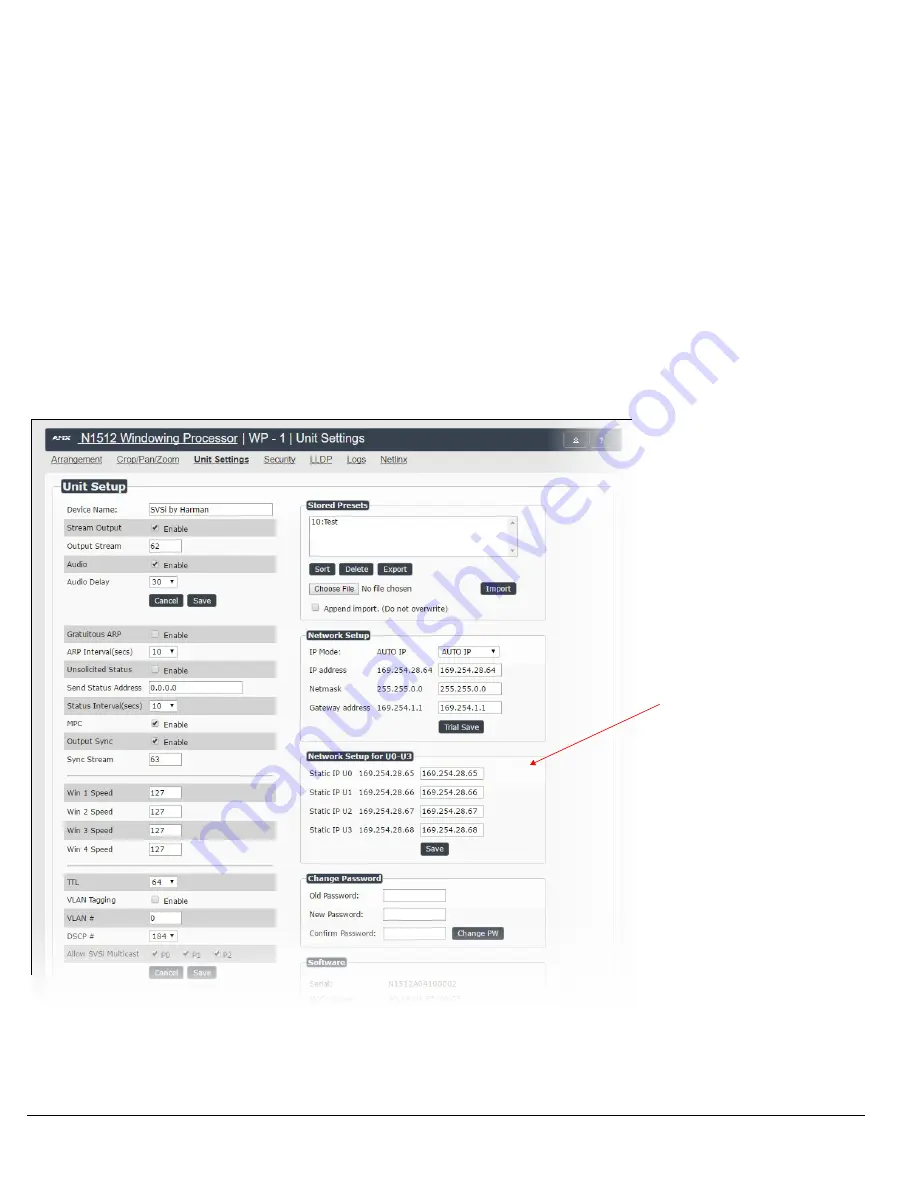
Unit Settings Page
The
Unit Settings
page (shown in FIG. 8) allows you to configure unit and network settings as well as import/export presets for your
Windowing Processor. Available options include:
•
Device Name
: Configure a user-friendly name for your unit.
•
Stream Output
: Enable this option prior to viewing the output of the N1512 with a Decoder. When enabled, you can route AV streams in
N-Able (or your other configuration choice) to the four windows and route the output of the N1512 to an N1000 Decoder to verify oper-
ations.
•
Output Stream
: If desired, modify from the default stream number. N-Able (or your other configuration choice) may also prompt for this
to be changed when the unit is first discovered.
In the
Network Setup
section on the
Unit Settings
page:
•
IP address
is required, and will be used as the control IP address.
• Configure the
Netmask
and default
Gateway
address
as needed or directed by IT personnel.
• Assign four static IP addresses to the four
U
ports (see screen shot below for more details).
NOTE: If you do need to make changes to the Network Setup section, click Trial Save once changes are made. If the control IP address is
different from the default, you will need to log in to the unit using its new IP address. Once re-logged back in, click Confirm to keep the
changes. If the unit is power cycled before the changes are confirmed, it will revert to its original IP address.
FIG.8 UNIT SETTINGS PAGE
Assign unique statice IP
addresses for each of the U
ports. These must be in the
same subnet as the rest of the
system (i.e., host computer,
Windowing Processor,
Encoders, etc.).


