background image

Modero X Series G5 Touch Panels

8

Modero X® Series G5 Touch Panels - Installation & Hardware Reference Manual

Sleep Button

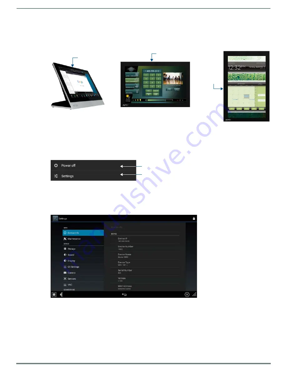
X Series G5 touch panels are operated using its integral touchscreen, as well as the 

Sleep

 button. The Sleep button is located in the 

in the center of the top panel of the device for tabletop and landscape wall-mount panels; it is located in the center of the left panel 

for portrait panels (see FIG. 2 on page 8). 

If the device has gone into its Sleep Mode, touching the touchscreen or pressing the Sleep button will reactivate it. Press and hold 

the Sleep button to access the Settings menu.

Powering On/Off X Series G5 Panels

Modero X Series G5 touch panels may be powered on by touching the 

Sleep

 button. To power off the panel, press and hold the 

Sleep button, and select 

Power Off

 on the on-screen menu (FIG. 3): 

Configuration and Programming

X Series G5 touch panels are equipped with a 

Settings

 menu that provides the ability to configure various features on the panels. To 

access the 

Settings

 menu, press and hold the Sleep button, and select 

Settings 

(FIG. 3). This opens the main Settings menu 

(FIG. 4): 

Information on the 

Settings

 menu, panel configuration, and programming is included in the 

Modero X Series G5 Programming 

Guide

, available at 

www.amx.com

.

NOTE: 

Note: Programming the Modero X Series G5 touch panels require the use of the latest versions of NetLinx Studio and 

TPDesign5, both available to download at www.amx.com.

Bluetooth Support

X Series G5 touch panels allow the use of Bluetooth keyboard and mouse combinations, using HID Profile v1.1. Using a keyboard 

and mouse with the device requires use of the MXA-BT Bluetooth USB Adapter (

FG5968-19

).

FIG. 2  

Sleep Button location - Tabletop, Landscape and Portrait layouts)

FIG. 3  

Sleep Button - Press to power on the panel; press and hold to access Power Off/Settings options

FIG. 4  

Main Settings menu

Sleep button

Sleep button

(on top panel)

(on top panel)

Sleep button

(on left panel)

Press to power of the panel

Press to access the Settings menu

Содержание Modero MXD-1001-L

Страница 1: ...TABLETOP TOUCH PANEL MXD 1901 PAN L 19 4 MODERO X SERIES G5 PANORAMIC LANDSCAPE WALL MOUNT TOUCH PANEL MXD 1901 PAN P 19 4 MODERO X SERIES G5 PANORAMIC PORTRAIT WALL MOUNT TOUCH PANEL MXT 1001 10 1 MO...

Страница 2: ...es and the point where they exit from the apparatus 11 ONLY USE attachments accessories specified by the manufacturer 12 USE ONLY with a cart stand tripod bracket or table specified by the manufacture...

Страница 3: ...INFORMATION The term IC before the radio certification number only signifies that Industry Canada technical specifications were met Le terme IC avant le num ro de certification radio signifie seulemen...

Страница 4: ...E INFORMATION This appliance is labeled in accordance with European Directive 2012 19 EU concerning waste of electrical and electronic equipment WEEE This label indicates that this product should not...

Страница 5: ...1 PAN Specifications 13 MXT D 1901 PAN 19 4 X Series G5 Panels 16 MXT 1901 PAN Tabletop 16 MXT 1901 PAN Specifications 16 MXD 1901 PAN Wall Mount Landscape Portrait 18 MXD 1901 PAN Specifications 18 M...

Страница 6: ...1 PAN Installation Dimensions 39 Power via 13 5V 41 Wiring a 13 5V Power Connection 42 Uninstalling the MXD 2001 PAN MXT 1901 PAN 42 Removing the Panel From Its Backbox 42 MXD 1001 MXD 701 Installatio...

Страница 7: ...ivers more The Modero X Series G5 Touch Panels covered in this manual include NOTE Note The X Series G5 panels described in this document represent a different product family than the X Series G4 touc...

Страница 8: ...a Settings menu that provides the ability to configure various features on the panels To access the Settings menu press and hold the Sleep button and select Settings FIG 3 This opens the main Settings...

Страница 9: ...is not enforced i e the TPDesign5 application will allow you include any number of video windows in the panel design attempting to display more than two active video windows at one time may have a ne...

Страница 10: ...riptions of each page and page option available in the G5 Settings Menu Firmware upgrades via the G5 Settings Menu Reset and Update page Using Content Sharing Using Gestures MXA MP and MXA MPL Program...

Страница 11: ...es Multi Preview Live FG5968 10 MXA MP Modero X S Series Multi Preview FG5968 20 CERTIFICATIONS FCC Part 15 Class B C Tick CISPR 22 Class B CE EN 55022 Class B and EN 55024 CB Scheme IEC 60950 1 IC IE...

Страница 12: ...Viewer Applications PDF JPEG BMP PNG TIFF GIF Remote Management VNC Server Video Conferencing Skype Audio Conferencing Audio Full Duplex Intercom FRONT PANEL COMPONENTS Light Sensor Photosensitive lig...

Страница 13: ...x 11 16 519mm x 242mm x 19mm WEIGHT 9 0 lbs 4 08 Kg POWER CONSUMPTION Full On 35 W 13 5V 2 6A Standby 7 W 13 5V 0 52A EXTERNAL POWER SUPPLY REQUIRED Requires one of these AMX power sources not includ...

Страница 14: ...1 requires MXA BT Bluetooth Adapter FG5968 19 VIDEO Supported Video Codecs MPEG 2 TS MPEG 2 Main Profile High Level up to 720p at 25 fps decode only MPEG 2 TS H 264 High Profile Layer 4 AAC LC up to 7...

Страница 15: ...over Kit Modero X Series Touch Panel FG5968 18 MXA CLK Modero X Series Cleaning Kit FG5968 16 Installation Template 20 3 68 5968 01 OPTIONAL ACCESSORIES MXA RMK 20 Modero X Series Rack Mount Kit FG596...

Страница 16: ...FG5968 10 MXA MP Modero X S Series Multi Preview FG5968 20 CERTIFICATIONS FCC Part 15 Class B C Tick CISPR 22 Class B CE EN 55022 Class B and EN 55024 CB Scheme IEC 60950 1 IC IEC EN 60950 UL 60950 1...

Страница 17: ...more information EMBEDDED APPLICATIONS Viewer Applications PDF JPEG BMP PNG TIFF GIF Remote Management VNC Server Video Conferencing Skype Conferencing Audio Full Duplex Intercom FRONT PANEL COMPONEN...

Страница 18: ...11 16 519mm x 175mm x 19mm WEIGHT 6 9 lbs 3 13 Kg POWER CONSUMPTION Full On 35 W 13 5V 2 6A Standby 7 W 13 5V 0 52A EXTERNAL POWER SUPPLY REQUIRED Requires one of these AMX power sources not included...

Страница 19: ...EG 2 TS MPEG 2 Main Profile High Level up to 720p at 25 fps decode only MPEG 2 TS H 264 High Profile Layer 4 AAC LC up to 720p at 25 fps encode decode MJPEG up to 720p at 25 fps decode only Supported...

Страница 20: ...C USB Port Cover Kit Modero X Series Touch Panel FG5968 18 MXA CLK Modero X Series Cleaning Kit FG5968 16 Installation Template 19 4 68 5968 02 OPTIONAL ACCESSORIES MXA FMK 19 Flush Mount Kit 19 4 Mod...

Страница 21: ...3 NXA ENET8 2POE Gigabit PoE Ethernet Switch FG2178 63 CERTIFICATIONS UL 60950 1 FCC Part 15 Class B C Tick CISPR 22 Class B CE EN 55022 Class B and EN 55024 CB Scheme IEC 60950 1 IC IEC EN 60950 RoHS...

Страница 22: ...touch and gestures scrolling transitions applications See TPD5 Operations Guide for more information EMBEDDED APPLICATIONS Viewer Applications PDF JPEG BMP PNG TIFF GIF Remote Management VNC Server V...

Страница 23: ...dscape MXD 1001 Specifications DIMENSIONS HWD Landscape 6 11 16 x 9 7 8 x 2 5 8 171mm x 252mm x 67mm Portrait 9 7 8 x 6 11 16 x 2 5 8 252mm x 171mm x 67mm WEIGHT 2 0 lbs 0 91 Kg POWER CONSUMPTION Full...

Страница 24: ...ile v1 5 Headset Profile v1 2 requires MXA BT Bluetooth Adapter FG5968 19 and MXA HST Bluetooth Handset FG5968 17 VIDEO Supported Video Codecs MPEG 2 TS MPEG 2 Main Profile High Level up to 720p at 25...

Страница 25: ...S MXA USB C USB Port Cover Kit Modero X Series Touch Panel FG5968 18 MXA CLK Modero X S Series Cleaning Kit FG5968 16 Installation Template 10 Modero X Series 68 5968 03 OPTIONAL ACCESSORIES MXA FMK 1...

Страница 26: ...witch FG2178 63 CERTIFICATIONS FCC Part 15 Class B C Tick CISPR 22 Class B CE EN 55022 Class B and EN 55024 CB Scheme IEC 60950 1 IC IEC EN 60950 UL 60950 1 RoHS WEEE compliant TOUCH SCREEN DISPLAY Di...

Страница 27: ...e Formats WAV MP3 as part of touch panel file only no USB storage Intercom Full Duplex VoIP SIP v2 0 GRAPHICS ENGINE AMX G5 G5 enhanced feature set supporting multi touch and gestures scrolling transi...

Страница 28: ...4 13 16 x 2 1 2 186mm x 122mm x 63mm WEIGHT 1 4 lbs 0 64 Kg POWER CONSUMPTION Full On 11 5 W maximum Standby 5 8 W Shutdown 1 W Start Up Inrush Current Not applicable due to PoE standard EXTERNAL POWE...

Страница 29: ...ofile v1 2 requires MXA BT Bluetooth Adapter FG5968 19 and MXA HST Bluetooth Handset FG5968 17 VIDEO Supported Video Codecs MPEG2 TS MPEG 2 Main Profile High Level up to 720p at 25 fps decode only MPE...

Страница 30: ...emplate 7 Modero X Series 68 5968 04 OPTIONAL ACCESSORIES MXA FMK 07 Flush Mount Kit 7 Modero X Wall Mount FG5968 71 MXA RMK 07 Modero X Series Rack Mount Kit FG5969 63 MXA MP Modero X S Series Multi...

Страница 31: ...ll as an additional USB port are located on the bottom of the device FIG 15 NOTE Refer to the Power via 13 5V section on page 32 for details on wiring a power connection The underside USB port as well...

Страница 32: ...screws instead of the pins on each side of standard captive wire connectors and using force to insert a standard captive wire connector may damage the device Wiring a 13 5V Power Connection To use the...

Страница 33: ...smaller than 1 00 in diameter 1 On a soft surface turn the MXT 1001 face down to access the bottom of the device 2 Remove the clamp holding the Ethernet cable FIG 19 3 Remove the Ethernet cable connec...

Страница 34: ...rete as well as with a closed volume such as between studs in an otherwise finished wall The diagram shows how heat generated by the device or other devices may have no way to escape and may build up...

Страница 35: ...e included locking tabs for different mounting options Once installed the panel is contained within a clear outer housing known as the Backbox FIG 22 This Backbox is removed when installing the device...

Страница 36: ...Hardware Reference Manual MXD 2001 PAN Dimensions FIG 24 provides dimensions for the MXD 2001 PAN FIG 24 MXD 2001 PAN Dimensions Notes Dimensions in parenthesis are in millimeters Additional detailed...

Страница 37: ...for the MXD 1901 PAN NOTE In order to ensure a stable installation the thickness of the wall material must be a minimum of 50 inches 1 27cm and a maximum of 875 inches 2 22cm FIG 25 MXD 1901 PAN Dime...

Страница 38: ...01 PAN FIG 26 MXD 2001 PAN L Installation Dimensions front view FIG 27 MXD 2001 PAN L Installation Dimensions side view Notes Dimensions in parenthesis are in millimeters These drawings show a Landsca...

Страница 39: ...ation Template as a guide NOTE Making sure that the actual cutout opening is slightly smaller than the provided dimensions is highly recommended This action provides the installer with a margin for er...

Страница 40: ...ply enough pressure to the screw head to keep the box flush with the wall this ensures that the locking tabs will tighten up against the inside of the wall The Backbox is clear to allow visual confirm...

Страница 41: ...lling the panel do NOT press on or near the center of the panel Too much stress at the center may damage the touch screen surface When installing the panel pressure should be applied toward the ends o...

Страница 42: ...e side covers on the left and right landscape or top and bottom portrait FIG 34 Note that FIG 34 shows the MXD 1901 PAN but the illustration applies equally to the MXD 2001 PAN Also note that FIG 34 s...

Страница 43: ...x accessory FG039 17 NOTE For typical mounting surfaces such as drywall use the locking tabs as the primary method for securing the Backbox to the surface For thin walls or solid surfaces use mounting...

Страница 44: ...lation Hardware Reference Manual MXD 1001 Dimensions FIG 37 provides dimensions for the MXD 1001 FIG 37 MXD 1001 Dimensions Notes Dimensions in parenthesis are in millimeters Additional detailed insta...

Страница 45: ...order to ensure a stable installation the thickness of the wall material must be a minimum of 50 inches 1 27cm and a maximum of 875 inches 2 22cm The mounting surface should also be smooth and flat F...

Страница 46: ...MXD 1001 FIG 39 MXD 1001 Installation Dimensions front view FIG 40 MXD 1001 Installation Dimensions side view Notes Dimensions in parenthesis are in millimeters These drawings show a Landscape panel T...

Страница 47: ...by removing any screws or nails from the drywall before beginning the cutout process 2 After ensuring proper placement cut out the mounting surface for the Backbox using the included Installation Temp...

Страница 48: ...portrait panel is essentially the same other than the vertical orientation Leave enough slack in the wiring to accommodate any re positioning of the panel FIG 43 shows the MXD 1001 Backbox installatio...

Страница 49: ...removal if necessary For additional strength 4 mounting screws not included may be secured through circular holes located at the left and right sides of the panel FIG 43 FIG 44 In order to prevent dam...

Страница 50: ...ing the Ethernet cable is desired a hole at least 1 00 2 54 cm in diameter is required in the surface to allow passage of the female RJ45 connector FIG 46 If using a smaller hole is unavoidable you wi...

Страница 51: ...rait of the MXD 1001 locate the seventh and eight ventilation holes from each edge on the row closest to the Backbox FIG 48 3 With a stout strong point i e push pin or straightened paper clip carefull...

Страница 52: ...ip for example carefully press into the access holes in either end of the molding until the snap is disconnected To facilitate the disconnection grasp the bottom of the panel Landscape or right side P...

Страница 53: ...er is available and to reply with a connection failure instantly if it is not Without using the ping feature a connection may still be attempted but a failure will take longer to be recognized NOTE If...

Страница 54: ...X does not assume responsibility for errors or omissions AMX also reserves the right to alter specifications without prior notice at any time The AMX Warranty and Return Policy and related documents c...

Отзывы: