

AMX Corporation reserves the right to alter specifications without notice at any time.
For full warranty information, refer to the AMX Instruction Manual(s) associated with your Product(s).
041-004-2959 1/06 ©2006
AMX Corporation. All rights reserved. The AMX logo is a trademark of AMX Corporation.
3000 RESEARCH DRIVE, RICHARDSON, TX 75082 • 800.222.0193 • fax 469.624.7153 • technical support 800.932.6993 • www.amx.com
93-2408-01
REV: A
Flat Surface Installation
It is recommended that you cutout the surface slightly smaller than what is outlined in
the installation drawings so that you can make any necessary cutout adjustments.
Before you begin, if you are using the 2-pin power connector, verify that the terminal
end of the power cable is not connected to a power source
1.
If assembled, remove the Mio Modero DMS from the backbox. Place a flathead
screwdriver between the tab of the backbox and the notch of the Mio Modero
DMS (see FIG. 2) and pry the two apart.
2.
Cut out the surface for the Mio Modero DMS backbox using the dimensions
shown in FIG. 3. A template is included to help you determine dimensions.
3.
Thread the CAT5/CAT6 and, if necessary, the power cables through one of the
provided breakaway access points on the backbox. Leave enough slack in the
wiring to accommodate any re-positioning of the unit.
4.
Insert the backbox into the cutout until the rim of the backbox is flush against
the wall.
5.
Insert and secure four #4-40 mounting screws (not included) into their
corresponding holes located along the sides of the backbox until it is flush
against the wall. Or use expansion clips at this time.
6.
Connect the 2-pin power connector and/or CAT5/CAT6 cables in the back of
the Mio Modero DMS. See FIG. 2 for port locations.
7.
Insert and fasten the Mio Modero DMS into the backbox, start at the top of the
device and tilt in toward the bottom.
Device Setup
The Mio Modero DMS Pinnacle is equipped with firmware pages that allow you to set
and configure various features of the device. Some menu items are compulsory,
Necessary Device Setup
, while other items are optional,
Optional Device
Setup
section on page 28
of the instruction manual.
To navigate the pages in the Mio Modero DMS Pinnacle, press
More...
to view more
options within the selected menu. Press
Return
to go back a page and accept
changes made.
Note:
Confirm your NetLinx master has the latest version of Nexus compliant
firmware. The firmware must be UDP and NDP settings compliant (v.323 or higher).
Accessing The Setup Page
If you have not loaded any pages on your Mio Modero DMS device, it will launch the
Setup page by default. Otherwise, press and hold in the middle of the slider for 3
seconds.
Necessary Device Setup
The following sections must be set on your Mio Modero DMS Pinnacle.
Device Calibration
From the Setup page, follow these steps:
1.
Select
Protected Setup.
If you do not have a password established on the Mio
Modero DMS Pinnacle, the device will not prompt you for one. Default pass-
word is
1988
.
2.
Select
Calibrate
.
3.
Touch each target on the screen as they appear. Once calibrated the Mio Mod-
ero DMS Pinnacle confirms and instructs you to touch the screen to continue.
You can now select
Return
and go back to the Setup page.
IP Settings
The configuration of the Mio Modero DMS Pinnacle requires you set the
communication protocol. Your options are either Static or DHCP. Consult the
Mio
Modero DMS & Mio Modero DMS Pinnacle
instruction manual for setting Static.
From the Setup page, follow these steps:
1.
Push
Protected Setup
. If you do not have a password established, the device
will not prompt you for one.
2.
Select
IP Settings
.
3.
Select
DHCP
.
4.
In the DHCP page, select
DHCP
to toggle the protocol between
DHCP
and
Static
.
5.
Select
Return
to accept that change.
Consult the
Mio Modero DMS & Mio Modero DMS Pinnacle
instruction manual for
setting a Host Name.
DMS Pinnacle Menu Navigation
Follow these tips to set your device information:
• Touch the top of the slider to move
UP
and the bottom of the slider to move
DOWN
through numerals.
•
Accept Char
enters the current value and moves the cursor to the right.
•
Backspace
moves the cursor to the left.
•
Clear
removes everything listed.
•
Abort
exits the edit page without keeping changes.
•
Done
accepts changes and returns to the previous page.
Master Connection
The Mio Modero DMS Pinnacle requires you establish the type of connection you
want made between it and your master. From the Setup page, follow these steps:
1.
Select
Protected Setup
. If you do not have a password established, the device
will not prompt you for one.
2.
Select
Master Connection
.
3.
Select
Connection Mode
.
4.
Select the listed mode to toggle through the available connection modes:
5.
Select
More...
to view the second page of the
Master Connection
menu.
6.
Select
Master Port
. The default setting for the port is
1319
. Select the master
port number to access the edit page and change this value.
See
DMS Pinnacle Menu Navigation
for help.
7.
After you have set your Master Port and selected
Done
, select
Return
to
finalize your changes and go back to the
Master Connection
page.
If you have enabled password security on your master you need to set the username
and password within the device.
8.
Select
Username
. If no username has been set, the field is blank. Select the
blank field just below
Username
.
See
DMS Pinnacle Menu Navigation
for help.
9.
After you have set your Username and selected
Done
, select
Return
to finalize
your changes and go back to the
Master Connection
page.
10.
Select
More...
11.
Select
Password
. If no password has been set, the field is blank. Select the
blank field just below
Password
.
See
DMS Pinnacle Menu Navigation
for help.
12.
After you have set your Password and selected
Done
, select
Return
to finalize
your changes and go back to the
Master Connection
page.
13.
Reboot device to confirm changes.
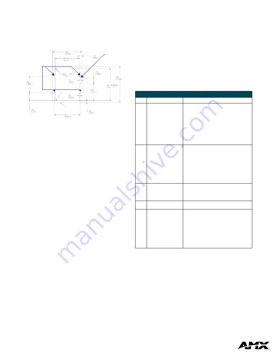
FIG. 3
Mio Modero DMS Installation Using Either Expansion Clips or #4-40 Screws
(2 PROVIDED)
DRYWALL EXPANSIONS CLIPS
IF UNIT IS INSTALLED USING
THIS NOTCH IS ONLY NEEDED
THESE 4 HOLES ARE ONLY REQUIRED
WHEN MOUNTING UNIT TO A SOLID
SECURE UNIT WITH #4 SCREWS.
SURFACE (PODIUM, DESK, ETC.).
BEZEL OUTLINE
CUTOUT
Only required for
solid surface mounting.
Use #4 screws.
Notch
Connection Modes
Mode
Description
Procedures
Auto
The device connects to the
first master that responds.
This setting requires you set
the System Number, this set-
ting is available in the
Master
Connection
menu.
Setting the System Number:
1.
Within the
Master Connection
menu,
select
System Number
.
2.
To change the System Number from what
is listed, select the System Number to
enter the edit page.
See
DMS Pinnacle Menu Navigation
for help.
3.
After you have set your System Number
and selected
Done
, select
Return
to
finalize your changes and go back to the
Master Connection
page.
URL
The device connects to the
specific IP of a master via a
TCP connection. This setting
requires you set the Master’s
IP.
Setting the Master IP:
1.
Select
More...
2.
Select
Master IP
.
3.
To change the Master IP from what is
listed, press the button next to the Master
IP number to enter the edit page.
See
DMS Pinnacle Menu Navigation
for help.
4.
After you have set your Master IP and
selected
Done
, select
Return
to finalize
your changes and go back to the
Master
Connection
page.
Listen
The device "listens" for the
master to initiate contact.
This setting requires you
provide the master with the
device’s IP.
Confirm device IP is on the Master URL list. You can set
the Host Name on the device and use it to locate the
device on the master. Host Name is particularly useful in
the DHCP scenario where the IP address can change.
NDP
(UDP)
The device is available via
Nexus Discovery Protocol.
Use the master web interface, NetLinx Studio or
commands to bind the DMS device to the master.
URL
(UDP)
The device connects to the
specific IP of a master via
UDP.
Setting the Master IP:
1.
Select
More...
2.
Select
Master IP
.
3.
To change the Master IP from what is
listed, press the button next to the Master
IP number to enter the edit page.
See
DMS Pinnacle Menu Navigation
for help.
4.
After you have set your Master IP and
selected
Done
, select
Return
to finalize
your changes and go back to the
Master
Connection
page.


