TDC-GPX2 Standard Board
ams Eval Kit Manual
Page 10
[v1-00] 2016-Oct-20
Document Feedback
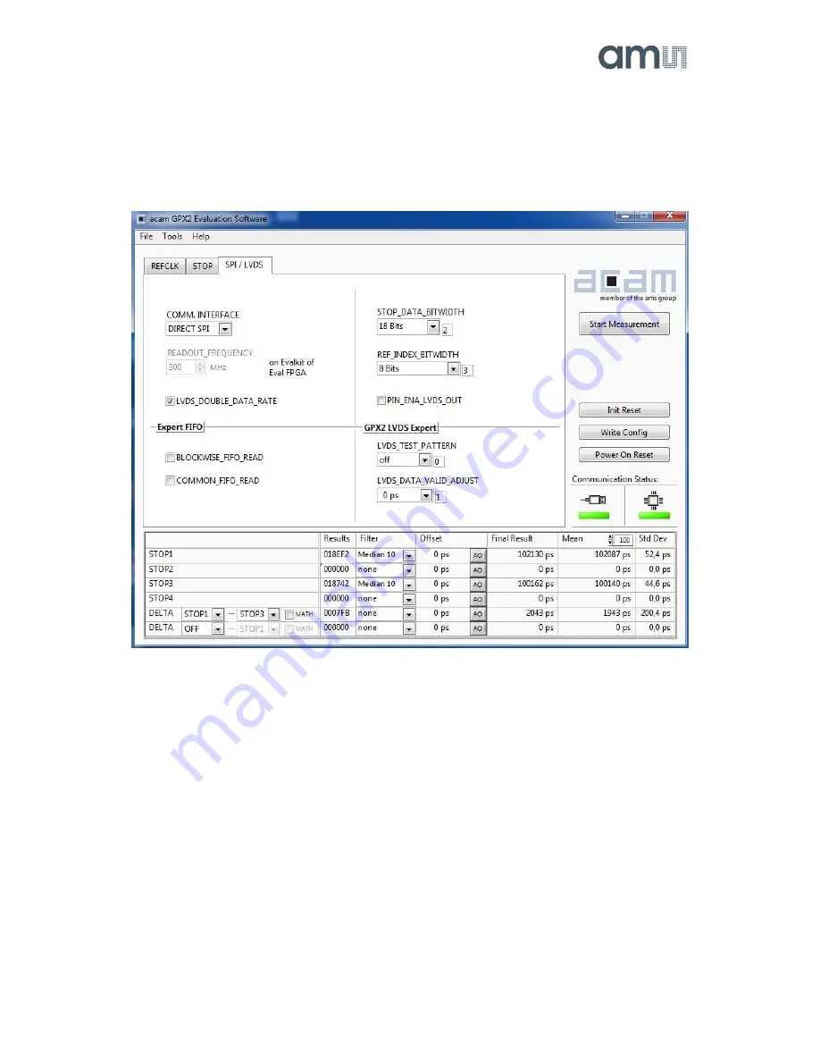
4.3
Interface Page
On this page the communication as well as the output data format is defined. In any case, on the
evaluation kit all communication is done via the on-board FPGA.
Figure 7: Kit Content


