CoreModule 420
Reference Manual
45
Chapter 4
BIOS Setup
Introduction
This chapter describes the BIOS Setup menus and the various screens used for configuring the
CoreModule 420. Some features in the Operating System or application software may require
configuration in the BIOS Setup screens.
This section assumes the user is familiar with general BIOS setup and does not attempt to describe the
BIOS functions. Refer to the appropriate PC reference manuals for information about the software
interface of the onboard ROM-BIOS. If Ampro has added to or modified the standard functions, these
functions will be described.
The options provided for the CoreModule 420 are controlled by the BIOS Setup Utility. BIOS Setup is
used to configure the CoreModule 420 features, modify the fields in the Setup screens, and save the
results in the onboard configuration memory. Configuration memory consists of portions of the CMOS
RAM in the battery-backed real time clock chip and the flash memory.
The Setup information is retrieved from configuration memory when the module is powered up or when
it is rebooted. Changes made to the Setup parameters, with the exception of the time and date settings,
do not take effect until the module is rebooted.
Setup is located in the ROM BIOS and can be accessed, when prompted using the <Del> key, while the
module is in the Power-On Self Test (POST) state, just before completing the boot process. The screen
displays a message indicating when you can press <Del>.
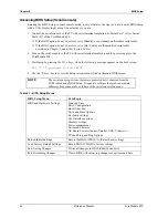
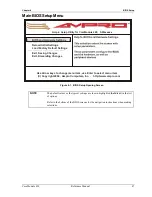
The CoreModule 420 Setup is used to configure items in the BIOS using the following menus:
•
BIOS and Hardware Settings
•
Reload Initial Settings
•
Load Factory Default Settings
•
Exit, Saving Changes
•
Exit, Discarding Changes
The main BIOS Setup menu offers the menu choices listed above and the related topics and screens are
described on the following pages. Table 4-1 summarizes the list of BIOS menus and some of the
features available for CoreModule 420.
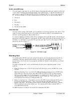
Accessing BIOS Setup (VGA Display)
To access BIOS Setup using a VGA display for the CoreModule 420:
1. Turn on the VGA monitor and the power supply to the CoreModule 420.
2. Start Setup by pressing the [Del] key, when the following message appears on the boot screen.
Hit <Del> if you want to run SETUP
NOTE
If the setting for
Memory Test
is set to Fast, you may not see this prompt appear on
screen if the monitor is too slow to display it on start up. If this happens, use the
<Del> key early in the boot sequence to enter BIOS Setup.
3. Use the <Enter> key to access the screen menus listed in the BIOS opening screen.
4. Follow the instructions at the bottom of each screen to navigate through the selections and
modify any settings.
Содержание CoreModule 420
Страница 1: ...CoreModule 420 PC 104 Single Board Computer Reference Manual P N 5001692A Revision A ...
Страница 6: ...Contents vi Reference Manual CoreModule 420 ...
Страница 10: ...Chapter 1 About this Manual 4 Reference Manual CoreModule 420 ...
Страница 22: ...Chapter 2 Product Overview 16 Reference Manual CoreModule 420 ...
Страница 50: ...Chapter 3 Hardware 44 Reference Manual CoreModule 420 ...
Страница 64: ...Appendix A Technical Support 58 Reference Manual CoreModule 420 ...
Страница 66: ...Appendix B Connector Part Numbers 60 Reference Manual CoreModule 420 ...
Страница 70: ...Index 64 Reference Manual CoreModule 420 ...
Страница 71: ......
Страница 72: ......

