Parts Identification ( Con’t )
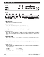
8. UNIT ADDRESS DIP SWITCHES
Example:
1000 0000 - Zone 1 to 8
0100 0000 - Zone 9 to 16
1100 0000 - Zone 17 to 24
DIP SWITCH 8
ON = MASTER (CH 1 - CH8)
OFF = SLAVE (CH 9 - CH248)
9. EMERGENCY OVERRIDE TERMINAL
10. AMPLIFIER ZONE OUTPUT CONNECTOR ( ZONE 1 - 8 )
DIP SWITCH 6
ON = TIMER 5 MIN
OFF = TIMER INFINITY
DIP SWITCH 7
ON = MIC OUTPUT
OFF = LINE OUTPUT
TD6080 | 8 CH DECODER / ZONE SELECTOR
PAGE 3
Each decoder caters for 8 channel outputs, thus each DIP setting shall comprise address for a gorup of 8 channels.
Address setting shall be using BCD codes.
External switch ( eg. fr emergency paging mic with dry contact ) can be connected here, which shall trigger the built in
relay when pressed. This shall then provide a dry contact in which would enable the installer to apply several functions
such as providing 24V DC output for volume controller overriding purpose, trigger external device or link to BAS
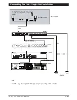
system, etc. Refer to page 10 for connection diagram.
Outputs from amplifiers are connected to these terminals and speaker zoning is configured to the respective
unit of amplifier. The user has the flexibility to configure the zoning system as each zone comes with single amplifier
output connection. Please observe polarity when terminating the amplifier / speaker zones and ensure that each
zone is not over overloaded ( max load 500W l00V line ).
DIP SWITCH 1 TO 8


