PAGE 6
CONNECTING TO ZONE SELECTORS
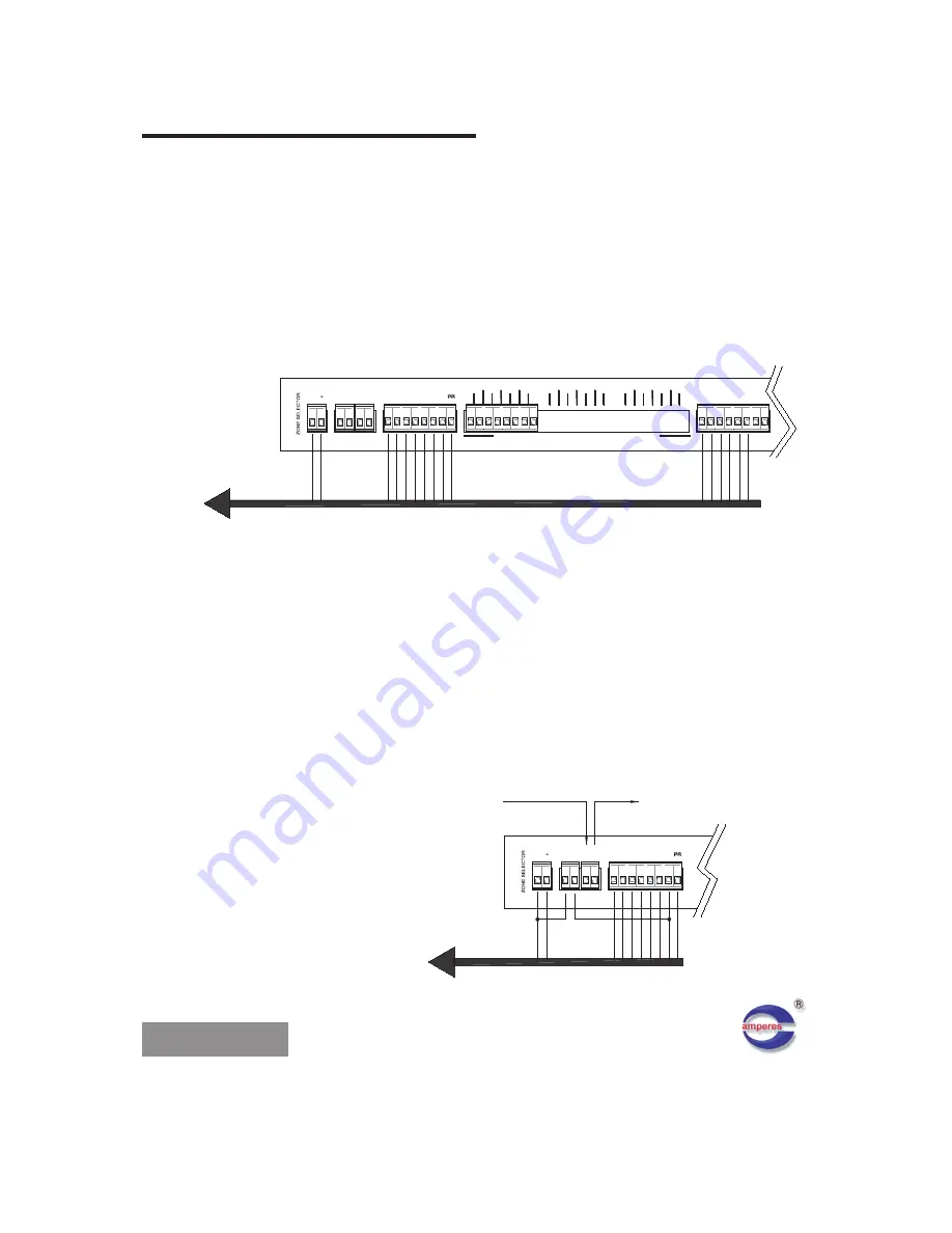
EXAMPLE 1 - CONNECTION TO ZONE SELECTOR - AMPERES ZS5121
The diagram below shows the connection of incoming paging microphone to the zone
selector - Amperes ZS5121. The All Call input (A) is connected to the either one of the
ports only.
For application of 6 zones, pin 7 to 12 from the D15 connector are not used.
The recommended connection between the paging mic and zone selector is below 30 m,
due to the voltage drop along the cable.
P
IN
1
5
C
H
A
S
SI
S
P
IN
1
P
IN
2
P
IN
3
P
IN
4
P
IN
5
P
IN
6
P
IN
1
3
P
IN
1
4
P
IN
7
P
IN
8
P
IN
9
P
IN
1
0
P
IN
1
1
P
IN
1
2
TRIG
RELAY
ZS
5
12
1
+
DC 24V
REMOTE SELECT
1
RELAY
CONT
5 6 A
2 3 4
AMPLIFIER INPUTS - ZONE OUTPUTS FOR ZONE 1 TO 6
AMP 6
1
0
0
V
AMP 3
C
O
M
ZON1
C
O
M
C
O
M
1
0
0
V
1
0
0
V
AMP 1
1
0
0
V
AMP 2
1
0
0
V
C
O
M
1
0
0
V
ZON2
C
O
M
ZON4
1
0
0
V
ZON3
1
0
0
V
C
O
M
1
0
0
V
AMP 4
C
O
M
AMP 5
1
0
0
V
C
O
M
ZON5
C
O
M
C
O
M
1
0
0
V
REMOTE SELECT
8
ZON6
1
0
0
V
C
O
M
7
C
O
M
10
9
A
12
11
-
TO
P
A
G
IN
G
M
IC
C
O
N
N
E
C
TO
R
EXAMPLE 2 - CONNECTION FOR VOLUME CONTROLLER OVERRIDE
Sometimes the operator would like to override the volume controllers or the patch panels
from the paging console by pressing ALL CALL, while other zone activation is only for
normal paging. The overriding of volume controllers shall require 24V DC for the activation
of their internal relay and this can be done using the paging mic and zone selector.
Some simple interlining connections at the remote triggering port shall be able to serve the
purpose with the diagram shown.
P
IN
1
4
RELAY
REMOTE SELECT
DC 24V
+
ZS
5
12
1
RELAY
TRIG
C
H
A
SS
IS
P
IN
1
5
P
IN
2
P
IN
1
P
IN
1
3
P
IN
6
P
IN
5
P
IN
4
P
IN
3
CONT
1
4
3
2
A
6
5
24V DC supply
to volume
controller /
patch panels
to paging microphone
D15 connector


