3
4
5
6
1
7
2
8
9
10 11
12
15
14
16
17
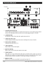
3. FRONT MIC INPUT JACK
Channel 1 balanced microphone input. Once inserted, it shall bypass the rear input connection.
4. INPUT LEVEL CONTROLS
Individual control knobs for input 1 to 6.
5. TONE CONTROLS
Bass and treble controls for mixed signals.
6. MASTER CONTROL
Master volume control for mixed signal; speaker and line outputs.
7. POWER SWITCH
Mains switch for ac input. Switching off the switch shall not disconnect the DC supply to the unit if it is
connected to back up battery. It is recommended that the DC back up is connected to the battery charger's
EM output instead of directly to the batteries. This shall prevent drainage of the battery bank.
100V line output can be channeled into 3 output zones and each zone can be selected via these switches
with ALL CALL. Alternatively, selection can also be done via remote paging microphone, ie. PM1060.
1. SPEAKER ZONE SELECTOR
2. LED INDICATORS
Front View:
Rear View:
19
LED indicators for Power, Protect mode and 4 segment output level meter.
13
18
8. MAINS AC CORD
Mains AC cord comes with standard British 3 pin plug with fuse rating of 5A.
Parts Identifications
PAGE 2
MA2000 SERIES | MIXER AMPLIFIER WITH 3 ZONE OUTPUT
CH1
CH2
CH3
CH5
CH6
MASTER
MIC
BASS
TREBLE
CH4
POWER
MA 2024
O
I
WARNING !
TO REDUCE THE RISK OF FIRE OR
ELECTRIC SHOCK DO NOT EXPOSE THIS
EQUIPMENT TO RAIN OR MOISTURE.
RISK OF ELECTRICAL SHOCK
DO NOT OPEN
CAUTION
CH3
CH5
CH6
CH4
MIC
LINE
MIC
LINE
MIC
LINE
MIC
LINE
CH3
CH4
CH5
CH6
MIC LEVEL (BALANCED/UNBALANCED)
LINE LEVEL
MIC LEVEL
PRIORITY MUTE
CH.1 / 2 / EXT.IN
MAX
CH3
CH5
CH6
CH4
MIC
LINE
MIC
LINE
MIC
LINE
MIC
LINE
CH3
CH4
CH5
CH6
MIC LEVEL (BALANCED/UNBALANCED)
LINE LEVEL
CH.1 / 2 / EXT.IN
MAX

