background image


Installation & Commissioning of Control & Monitoring Add On’s 


Page: 8 


4.5 

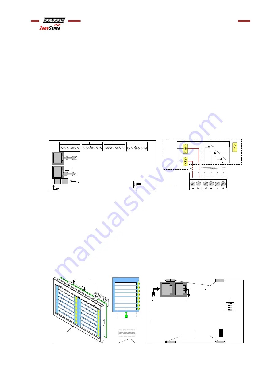
Fan Termination Board BRD25FTB 


The Fan Termination Board interfaces between the Fire Fan Module and the plant/equipment it 
controls via the 24 volt 250mA Start, Stop, current limited, relay outputs and monitor inputs. 
Programmable monitoring of the field equipment is achieved using 0 volts as an input level to 
indicate run, fault and stop conditions of that equipment. Monitoring is programmed in the 
Function Menu for a 3, 4 or 5 Wire Start / Stop, Run, Fault, Stop & Common functions. The inputs 
are protected by way of resetable transorbs and resistive / capacitive networks. 


Quiescent Current: 6.5mA 


Connectors 

CN1 

RS485 Control IN from previous board or Main Card 

CN2 

RS485 Control OUT to next board or LK1 EOL termination is applied 

CN3 

27 VDC IN from CN10 of the Main Card or CN4 of the previous board 

CN4 27 

VDC 

OUT 


Terminal Blocks 
TB2 – 5

   Are used to connect the fan control and monitoring wiring to the board. 


SW1

TB4

TB3

TB2

LK1

TB5

EOL Termination

0V

+2

7V

POWER

Address SW

FAN 1

FAN 1

STOP

COM

STOP

FLT

RUN

FAN 2

STOP

COM

STOP

FLT

RUN

START

FAN 3

FAN 3

STOP

COM

STOP

FLT

RUN

START

FAN 4

COM

STOP

FLT

RUN

START

FAN 4

STOP

START

FAN 2

CN1

CN2

CN3

CN4

RS485 Control in from CN2 of Previous Board or CN5 of the Main Card

RS485 Control  Out to Next  Board or Link 1  EOL is Applied

27V In from CN 10 on the Main Card or CN4 of the Previous Board

27V Out to Next Board if Applicable

1   2   3  4

O N


STOP

COM

STOP

FLT

RUN

START

TB 2, 3, 4 or 5

Cabling from FACP

to Plant / Equipment

1        2         3         4         5        6

FAN CONTROL

SOLID STATE OR

RELAY INTERFACE

FAN MONITORING

0V

INPUTS 1, 2 & 3

+24V O/Ps

RUN


Figure 11: Fan Termination Board Layout and Typical I/O Wiring 


4.6 

General Indicator Card BRD25GIB -A 


IMPORTANT 


Note: 

The Cards BRD25GIB –A, B, C and D all have a common PCB. What sets them apart from 

each other is not only the function they perform but how the componentry is loaded onto the card 
to perform that function.  


This Card indicates / displays the status of the inputs on the 16 Way Input Termination Board by 
way of Program selectable tri-coloured LED’s with its function being identified on the front panel 
by slip in labels.  


Quiescent Current: 

3 to 3.5mA depending on the application 


Card & PCB Securing Tabs

( Top & Bottom )

PCB

Clip On

Plastic Surround 

( Push down here and pull

out to remove and insert labels )

Lettering on slip in

labels must be at

least 5mm in height.

Windows for

Slip in Label

Slip In Label


K2 Termination

Link

In

Out

Address 

 Switch

Set to 1

1  

 2   3 

 4

ON

C

N

1

C

N

2

CN1: Communications & 27V IN 

from CN2 off the previous Front

Panel Card or CN9 on the Main Card

CN2: Communications & 27V OUT to Next Front Panel Card.

If Unsed the Termination Link Must be Inserted.

Top Front Card &

PCB Securing Clips

Bottom Front Card &

PCB Securing Clips


Figure 12: Front Panel Card Layout   

Figure 13: Front Panel Card & PCB Layout 


Содержание ZoneSense Plus

Страница 1: ...PAC SYSTEM IS NORMAL ALARMS DELAY ACTIVE FIRE FAULT FIRE OUTPUT ON ALARMS STATUS DISABLED NORMAL ENABLE EVACUATE RESET SILENCE BUZZER SILENCE RESOUND OVERRIDE F F Fi i ir r re e e A A Al l la a ar r rm m m C C Co o on n nt t tr r ro o ol l l P P Pa a an n ne e el l l E E EN N N5 5 54 4 4 2 2 2 4 4 4 1 1 19 9 99 9 97 7 7 Our aim is to provide Consistently Excellent Service in the eyes of our custom...

Страница 2: ......

Страница 3: ...5 Fan Termination Board BRD25FTB 8 4 6 General Indicator Card BRD25GIB A 8 4 7 Switch and Indicator Card BRD25GIB B 9 4 8 Zone Mimic Indicator Card Int Pwr BRD25GIB C 9 4 9 Zone Mimic Indicator Card Externally Powered BRD25GIB C 10 4 10 LED Annunciator Master LAM BRD25GIB E 10 4 11 Sounder Board BRD25SOPB A 11 5 Agent Release 11 5 1 Operation 11 5 2 Agent Release Module BRD25ARB A 14 5 3 Local Con...

Страница 4: ... to the installation and commissioning of the ZoneSense PLUS FACP 3 observe anti static pre cautions at all times and 4 if a problem is encountered or there is any doubt with respect to the operational parameters of the installation the supplier should be contacted 1 3 References ZoneSense PLUS Technical Manual ZoneSense PLUS Operation Programming Manual ZoneSense PLUS Installation and Commissioni...

Страница 5: ...p to a distance of 1 2km from the panel itself The external cabling 2x2 shielded pair plus power is wired to TB2 and earth Note If a fault occurs on the communications line the common FAULT and SYSTEM FAULT LED S will be illuminated The fault details can be displayed by selecting the Faults Menu Remote Cards The number of cards that can be installed on the external communications bus are 8 x Remot...

Страница 6: ...o the FACP Note The Configuration label should be updated once the panel has been upgraded 4 Installation and Wiring of Add On Cards and Boards CAB1925 to Batteries CAB1902 CAB1905 CAB1911 TO MAINS EARTH CN1 CN2 CN2 CN1 ALARM 2 N C COM N 0 BATT FAIL N C COM N 0 ISOLATE N C COM N 0 FAULT N C COM N 0 ALARM 1 N C COM N 0 TB1 TB5 POWER 0V 27V 0V 27V CN2 CN1 CN3 CN4 POWER 27V 0V CN1 CN2 27v Power fitte...

Страница 7: ...1 LCS 2 INSERT LK1 INSERT LK1 INSERT LK1 If Agent Release is fitted to the FACP there will be an Agent Termination Board mounted on the Backpan Local Control Stations can then be fitted at some location remote from the FACP These LCS s communicate with the ATB via a second RS485 bus hence the last LCS in the chain will have to be terminated Note If Backpan boards AND remote facilities are fitted t...

Страница 8: ...3 4 O N ON Inputs 1 2 3 4 0V Inputs 5 6 7 8 0V Inputs 9 10 11 12 0V Inputs 13 14 15 16 0V 0V 16 Inputs are Voltage Free Contacts TB9 TB8 TB7 TB6 TB5 TB4 TB3 TB2 8 0 Volts Input 1 27 Volts In from CN10 on the Main Card or CN4 of the previous internal board 2 Select an appropriate length cable from those supplied to connect Comms 27V Note Only the first 8 Voltage Free Contacts are functionally progr...

Страница 9: ... Label Card PCB Securing Tabs Top Bottom PCB Clear Plastic Clip In Label Clip On Plastic Surround Push down here and pull out to remove and insert labels WINDOWS WINDOWS FOR SLIP IN LABELS Lettering on slip in labels must be at least 5mm in height K2 Termination Link In Out Address Switch Set to 1 1 2 3 4 ON C N 1 C N 2 CN1 Communications 27V IN from CN2 off the previous Front Panel Card or CN9 on...

Страница 10: ... 1 EOL is Applied 27V In from CN 10 on the Main Card or CN4 of the Previous Board 27V Out to Next Board if Applicable 1 2 3 4 ON STOP COM STOP FLT RUN START TB 2 3 4 or 5 Cabling from FACP to Plant Equipment 1 2 3 4 5 6 FAN CONTROL SOLID STATE OR RELAY INTERFACE FAN MONITORING 0V INPUTS 1 2 3 24V O Ps RUN Figure 11 Fan Termination Board Layout and Typical I O Wiring 4 6 General Indicator Card BRD2...

Страница 11: ...ne Mimic Indicator Card connects to the FACP 27 volt power supply and the internal communications bus for indication control The card provides remote visual indication of any Zone in an Alarm and or Fault Isolate condition A maximum of 8 of these cards can be connected to or daisy chained together on any one system Slip in labels identify the monitored Zone The Alarm LED s flash for an un acknowle...

Страница 12: ...to an FACP Card PCB Securing Tabs Top Bottom Lettering on slip in label must be at least 5mm in height Slip In Label PCB Alarm Disable Fault Windows for Slip in Label FIRE FAULT DISABLED ALARMS STATUS FIRE OUTPUT STATUS TEST DELAY ACTIVE POWER LAMP TEST SILENCE BUZZER FIRE FAULT DISABLED Release of the Clip On Surround Metal Cabinet Push down here and pull out to remove and insert label ABS Cabine...

Страница 13: ...ch at the Agent Release Module is the only keyswitch with a Disable selection and has the highest priority Hence when the keyswitch is in the Disable position all other keyswitches are ignored and the agent control system is in the Disabled mode Next priority is Manual Only If any keyswitch is in Manual Only providing the keyswitch at the Agent Release Module is NOT in Disable then the board is in...

Страница 14: ...pressure switch input on the termination card is activated or immediately depends on the pressure switch configuration 9 FACP to activate the FIRE output and light the FIRE LED The discharge sequence can be interrupted by the activation of the Hold input Activation of the Hold input prevents the release of the agent When the Hold switch is released the pre release delay is restarted While the Hold...

Страница 15: ...NCE RESOUND button at the FACP This action will also silence the alarm outputs at the FACP and the sounder outputs on the 8 way sounder board if fitted If the SILENCE RESOUND button is depressed again to instigate the RESOUND facility then the stage 1 and stage 2 outputs will be re activated as will the onboard alarm outputs and sounder outputs on the 8 way sounder board if fitted Lock Off Valve W...

Страница 16: ...LD AGENT SELECT MANUAL ONLY Figure 20 Exploded View of Module and Front Panel Layout Controlled Access It is a requirement that control be secured from unauthorised use For this reason a key switch has been included in the control process DISABLED AUTO MANUAL MANUAL ONLY Disabled Manual Only Auto Manual Keyswitch In disabled mode the selected activation circuit is electrically isolated from the ac...

Страница 17: ...s not used CN2 will carry a link so as to activate the panel 5 3 Local Control Station BRD25ARB B Except for the agent select button and the keyswitch only offering the Auto Manual and Manual Only selection the Local Control Station has the same indicators and controls as the Agent Release Module AUTO MANUAL MANUAL ONLY MANUAL HOLD MANUAL RELEASE ACTIVATED AUTO RELEASE ACTIVATED RESERVE AGENT TRIG...

Страница 18: ...l agent activation circuit is selected RESERVE AGENT Reserve Agent Yellow in colour Lit when the reserve agent activation circuit is selected BLOCKED MODE Blocked Mode Yellow in colour Lit when the lock off valve has been activated MANUAL HOLD Manual Hold Yellow in colour Lit when a Hold button is depressed on an LCS TRIGGER ZONE DISABLED Trigger Zone Disabled Yellow in colour Lit when any of the ...

Страница 19: ...sabled Hold Cutout Cutout RS 485 OUT TB2 TB1 SW2 K1 HY1 CN5 BUZZER BZ1 INTER LOCK COM Termination Link Address Switch EC3AW 3V3 POWER SUPPLY COM 27V Out 0V 27V In 0V _ _ RS 485 IN _ 1 2 3 4 O N CN8 CN2 Key Switch Manual Release Cutout Cutout Figure 24 Top PCB Layout Figure 25 Bottom PCB Layout 5 5 Agent Release Termination Board BRD25ATB Figure 26 Agent Termination Board PCB Layout LK1 Q2 SW1 U5 U...

Страница 20: ...red to TB5 1 2 EOL required 10KΩ and b un monitored via RL5 N O contacts wired to TB5 3 4 7 Stage 2 output initiates the visual and audible Fire Alarm and Do No Enter warnings a Monitored via RL6 C O contacts wired to TB6 1 2 EOL required is 10KΩ and b Un monitored via RL3 N O contacts wired to TB6 3 4 8 Release Main actuating circuit monitored 10KΩ EOL required via TB7 1 2 2A current limited Rele...

Страница 21: ...t Limited to1A Figure 29 Gas Fired Wiring Figure 30 System Inoperative Wiring As can be seen from above the Gas Fired Output can be wired to any interfacing or 1A monitoring circuit that requires a closed relay contact to indicate a change of state This could be a relay or a solid state device System Inoperative Outputs 27V 1A to supply interfacing signage and aural alarms to indicate the system h...

Страница 22: ...CEL MENU ENTER PRESS THESE KEYS TO SET YES NO YES MENU ENTER UPDATE PROGRAM FACTORY SET CAN NOT BE CHANGED EXAMPLE SET RESOUND TO YES THEN MOVE TO ALARM MOVE TO ALARM YES NO IF THESE 4 OPTIONS ARE NOT SET TO YES THEY WILL NOT APPEAR IN THE TEST MENU ENTER PASSWORD FACTORY DEFAULT PASSWORD IS 3333 PASSWORD 0000 MENU ENTER PASSWORD 0100 PASSWORD 0120 PASSWORD 0123 MENU ENTER PASSWORD ACCEPTED EXAMPL...

Страница 23: ...7 MENU ENTER RELAY 3 MENU ENTER SELECT RELAY 3 O N OFF MENU ENTER UPDATE MENU MENU ENTER IN THIS EXAMPLE RELAY 3 IS ACTIVATED BY ZONES 1 4 OR 8 WHEN IN ALARM OR I P s 1 3 OR 7 OF THE I P BOARD ARE ON TURN OFF 2 3 5 6 7 TURN ON 1 3 7 O N OFF MENU ENTER UPDATE MENU MENU ENTER TO EDIT DISPLAY TEXT USE SELECT ZONE MENU ENTER TO MOVE THROUGH THE ALPHABET NUMBERS TO MOVE THROUGH THE WORD MENU ENTER EDIT...

Страница 24: ...N DISABLE OFF ON BATT FAIL OFF ON ALARM 2 OFF ON RELAY 1 OFF ON RELAY 2 OFF ON RELAY 3 OFF ON RELAY 4 OFF ON RELAY 5 OFF ON RELAY 6 OFF ON RELAY 7 OFF ON RELAY 8 OFF ON FAN 1 OFF ON FAN 2 OFF ON FAN 3 OFF ON FAN 4 OFF ON AGENT OFF NORM SNDR 1 OFF NORM SNDR 2 OFF NORM SNDR 3 OFF NORM SNDR 4 OFF NORM SNDR 5 OFF NORM SNDR 6 OFF NORM SNDR 7 OFF NORM SNDR 8 OFF NORM INPUT 1 OFF ON INPUT 2 OFF ON INPUT ...

Страница 25: ... CANCEL PRESS CANCEL AT ANY TIME TO BACK OUT OF THE MENU MENU ENTER MENU ENTER MENU ENTER CANCEL MENU ENTER PRESS THESE KEYS TO SET YES NO YES MENU ENTER UPDATE PROGRAM FACTORY SET CAN NOT BE CHANGED EXAMPLE SET RESOUND TO YES THEN MOVE TO ALARM MOVE TO ALARM YES NO NOTES TO ADD OR DELTE FROM THE SYSTEM SET TO YES OR NO AND THEN GO TO THE PROGRAM MENU TO SET THE OPERATIONAL PARAMETERS IF THESE OPT...

Страница 26: ...NTER CANCEL MENU ENTER ZONE S C ZONE ALARM MENU ENTER ZONE FAULT EOL RES 6K8 EOL RES 10K PRESS SW N C SELECT ZONE MENU ENTER MENU ENTER ACF ISOALTE ACF ISOALTE PRESS ACF TO ISOLATE CIRCUITS EXTERNAL TO FACP SET 0 60 SEC SET 0 60 SEC SET 1 TO 4 RELEASE CONSTANT TO MOVE THROUGH THE ALPHABET NUMBERS TO MOVE THROUGH THE WORD MENU ENTER EDIT TEXT PRESS SW NONE MENU ENTER SET ZONE 12345678 MENU ENTER ME...

Страница 27: ......

Страница 28: ...ers Drive Osborne Park 6017 Western Australia Tel 61 8 9242 3333 Fax 61 8 9242 3334 Email info ampac net EUROPE AMPAC EUROPE LTD Unit 1 Norden Court Alan Ramsbottom Way Great Harwood Blackburn England BB6 7UR Tel 44 0 1254 880 201 Fax 44 0 1254 880 202 Email info eu ampac net NEW ZEALAND AMPAC INDUSTRIES LTD Unit 4 101 Diana Drive Glenfield Auckland New Zealand Tel 64 9 443 8072 Fax 64 9 443 8073 ...

Отзывы: