background image


2:  Installation 

 Hardware reference manual


© 2012 Advanced Micro Peripherals 
Document version A.00


3


9


Jumpers and connectors 

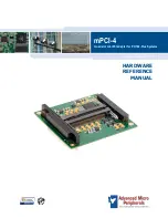
The following diagram shows the location of the jumpers and connectors available on 
the mPCI-4:  


PCI104


JP1


JP2


J1


J2 (underside)


J3


J4 (underside)


LEVEL1


PC/104-

Plus 

bus


Содержание mPCI-4

Страница 1: ...HARDWARE REFERENCE MANUAL mPCI 4 Quad slot miniPCI adapter for PC 104 Plus Systems Document version A 00...

Страница 2: ...s been carefully checked and is believed to be reliable However Advanced Micro Peripherals Ltd AMP makes no guarantee or warranty concerning the accuracy of said information and shall not be responsib...

Страница 3: ...ion A 00 3 Contents 1 Introduction 4 Features 5 mPCI 4 at a glance 5 Technical specification 6 Ordering information 7 Anti static handling 7 RoHS compliance 7 2 Installation 8 System requirements 8 Ju...

Страница 4: ...uses active PCI PCI bridging to support 4x miniPCI cards in a single PC 104 Plus stack location This allows the mPCI 4 to consume only 1 set of PCI resources and allows up to 4 mPCI 4 cards to be use...

Страница 5: ...dge for efficient use of system resources PC 104 Plus form factor Extended temperature range option Native driver support for Windows and Linux mPCI 4 at a glance Jumpers for IDSEL card and PCI card i...

Страница 6: ...terface 4x miniPCI Type III slots On board 3 3V power supply can provide up to 1A per slot System Requirements Spare REQ GNT on PC 104 Plus Bus 5V 3 3V signaling PC 104 Plus Bus Mechanical Standard 3...

Страница 7: ...charge the boards are supplied in anti static packaging When handling a board observe the following anti static precautions to alleviate risk of damage Remove the board s from the packaging only when...

Страница 8: ...ls Document version A 00 8 2 Installation System requirements Processor Pentium class CPU at 500MHz or faster Memory 512MB or greater Bus PC 104 Plus with 3 3V or 5V logic tolerance Operating system W...

Страница 9: ...anual 2012 Advanced Micro Peripherals Document version A 00 3 9 Jumpers and connectors The following diagram shows the location of the jumpers and connectors available on the mPCI 4 PCI104 JP1 JP2 J1...

Страница 10: ...pers and connectors All illustrations on these pages are shown in the same orientation as the photograph above unless otherwise stated Connector Signal See PCI1 PC 104 bus PCI104 Bus connector JP1 JP2...

Страница 11: ...s the first miniPCI slot behind the bridge This is assigned bridge resource IDSEL0 PCICLK0 REQ0 GNT0 J2 miniPCI Slot 2 miniPCI Type III slot located on underside of board This is the second miniPCI sl...

Страница 12: ...he mPCI 4 on the PC 104 Plus stack This setting routes the appropriate IDSEL PCICLK REQ and GNT signals to the PCI bridge chip on the mPCI 4 The following configurations are valid Jumpers IDSEL PCICLK...

Страница 13: ...determine how the miniPCI interrupts are routed to the swhich of the four PCI interrupts service the mPCI 4 card on the PC 104 Plus stack The following configurations are valid Jumpers J1 INTA J1 INTB...

Страница 14: ...anced Micro Peripherals Document version A 00 3 14 mPCI 4 card installation The mPCI 4 is supported by drivers provided as standard with most OS If you are using a recent BIOS version and operating sy...

Страница 15: ...eripherals Ltd 1 Harrier House Sedgeway Business Park Witchford Cambridge CB6 2HY United Kingdom Tel 01353 659500 Fax 01353 659600 E mail sales ampltd com Web www ampltd com Technical support Comprehe...

Отзывы: