


14
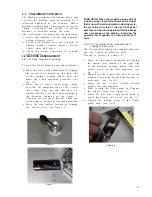
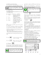
4.9.3 Frontal clamp adjustment
The Front Clamp bar has a series of holes in
it. By lifting the bar you can move it from its
initial position and reposition it forward or
backward.
To lock the bar it is sufficient to insert it
into the proper peg in the center of the guide
c h a n n e l .
To properly position the Horizontal Clamp,
operate as follows:
1. lift the bar from its peg about 10 - 15 mm
and move it forward until reaching the
moulding to be assembled;
2. lower the bar & allow it to drop over the
peg to lock it in the new position.
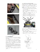
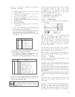
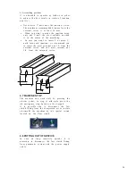
4.9.4 Fence adjustment
The machine is equipped with a special fence
composed of 2 different parts.
Each fence side is equipped with a knob that
allows it to tilt the moulding supports.
This fence use is recommended to assemble highly
profiled mouldings.
Furthermore, if the moulding rolls forward or
backwards as the front clamps engages, you can
adjust the tilting fence to compensate the
e f f e c t .
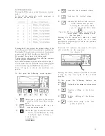
In addition to 90 degrees junctions , the Mitre-
Mite VN 4 Memory Program can be used also for
6-sided (120 degrees) or 8-sided frames (135
degrees), by properly positioning the back fence
s u p p o r t s .
Proceed as follows to modify the position of
back fence supports:
•
use a 5 mm Allen wrench and remove the
outside screw on the fence parts
•
loosen the inside screw slightly and position
the fence in the corresponding tapped holes
located on the working area.
The proper positioning of the back supports can
be obtained by using a special template, which
is included with the machine.
Care must be taken to ensure that the 120° or
135°angle is perfectly centered on the internal
vertex of the V-nail head.Use the center line
of the template to do this.
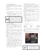
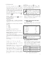
4 . 9 . 5 Working pressure adjustment
The working pressure must be adjusted to the
hardness of the mouldings to be assembled.
The pressure regulation permits you to change
the clamping pressure of mouldings to be
a s s e m b l e d .
Too high of a working pressure can cause a poor
junction and (especially on small-size frames)
the mouldings can be crushed.
Too low of a working pressure can cause an
incomplete insertion of the V-nails into the
f r a m e .
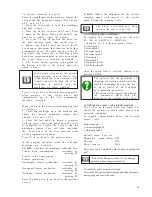
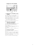
The working pressure is adjusted by means of
the regulator on the panel near the pressure
gauge (see fig. 13).
Proceed as follows to adjust the working
p r e s s u r e :
1. Pull up the regulator cap about 3÷4 mm to
unlock it
2. Turn it clockwise to increase the pressure
and counter-clockwise to decrease it.
3. Push the regulator cap back down, to lock it
into position
The suggested pressures are:
Soft woods
(samba,........) 30- 40 PSI
Medium
(ramin,........) 40 - 60 PSI
Very hard woods
(oak)
60 - 80 PSI
The above listed values apply to 7 and 10 mm high V-nails.
Increase the pressure by 10 % for 15 mm high V-
n a i l s .
When stacking 2 or more V-nails, increase the
working pressure by 10/15 %.
Figure 13
In case of continued use without
removing the bar from its position,
it is possible to fix it to the peg
using the proper screws. In case of
shipment, we suggest to clamp the
bar by using the supplied screw knob.
DO NOT ADJUST the pressure
if the machine is not
connected to the air supply
l i n e .
Содержание Mitre-Mite VN4 MemoryProgram
Страница 1: ......
Страница 32: ...32...
Страница 33: ...33...
Страница 38: ...38 ATTACHMENT C PLATES DISLOCATION...
Страница 41: ...41...