background image

72

ASC110/ASC130/ASC150/ASC200/ASC250

2.6.

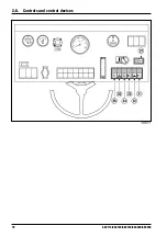
Controls and control devices

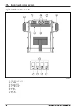
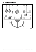
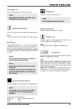
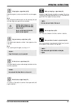
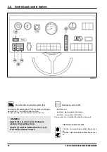
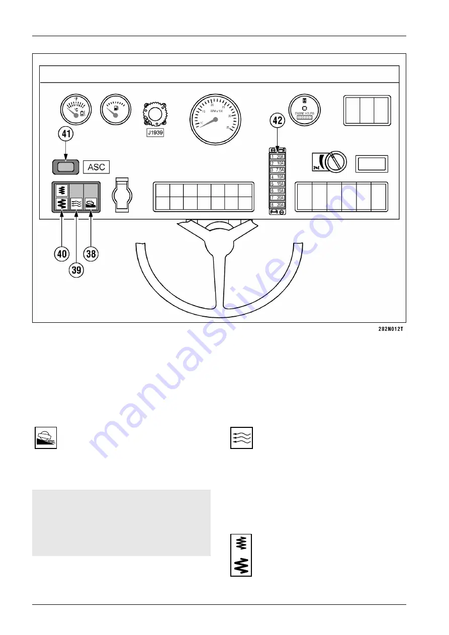
Drum traction slip control switch (38)

Located on the control panel if the machine is not equip-
ped with ASC - Anti Slip Control function.
The lamp in the switch indicates the function on.

! WARNING!

Apply traction slip control only for driving up to
platforms of transporting vehicles.

Selector (2) must be off while switch (38) is on. At
the same time, vibration is locked.

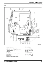
Heating fan switch (39)

position - off

position - high speed of fan motor

position - low speed of fan motor

Fan ensures air circulation inside the cabin only.

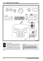
Vibration pre-selector (40)

Position - low amplitude and high frequency is
on
Position - high amplitude and low frequency is
on

Содержание ASC 130

Страница 1: ...Operating manual E ASC 130 Cummins Tier II 5 2006...

Страница 2: ...C 130 We preserve the right for changes at pictures and data for improving the manual s quality Overprint and copying of any kind and also individual paragraphs is conditioned by our written approval...

Страница 3: ...s therefore absolutely necessary to provide the operator with these instructions and to ensure that he reads them carefully before using the road roller This aids training comprehension during the fir...

Страница 4: ...4 ASC 130...

Страница 5: ...roller ASC 130 S N LWA 107 dB A LWA 108 dB A SZZPLS a s T anovsk ho 622 11 163 04 Praha 6 Czech Republic Notified body 1016 internal control of production according to Annex VI Directive 2000 14 EC h...

Страница 6: ...ASC 130...

Страница 7: ...5 ASC 130 NOTICE As used in this operating manual the terms right left front and rear indicate the sides of the machine moving forward...

Страница 8: ...23 1 3 7 Steering 23 1 3 8 Vibratory Drum 24 1 3 9 Hydrostatic Drive of Travel 24 1 3 10 Hydrostatic Drive of Vibration 25 1 3 11 Hydraulic Oil Tank 25 1 3 12 Lifting and lowering of the Hood and the...

Страница 9: ...of the machine 84 2 7 1 Starting the engine 84 2 7 2 Travel and reversing without vibrations 87 2 7 3 Travel with vibration 89 2 7 4 Stopping the machine and engine 90 2 7 5 Emergency stopping 91 2 7...

Страница 10: ...37 3 6 3 Checking oil in the hydraulic tank 138 3 6 4 Checking the engine belt 139 3 6 5 Checking the condition of the ventilator 139 3 6 6 Checking the engine inlet piping 139 3 6 7 Checking the vacu...

Страница 11: ...nnet and the driver s post 171 3 6 31 Exchanging the engine cooling liquid 172 3 6 32 Checking torsion vibration damper of the engine 174 Maintenance As Needed 175 3 6 33 Exchanging cleaner elements o...

Страница 12: ...10 ASC 130...

Страница 13: ...11 ASC 130 1 SPECIFICATION MANUAL ASC 130...

Страница 14: ...soils and rockfills up to the layer thickness of 70 cm 27 5 in gravels up to the layer thickness of 100 cm 39 4 in Maximal allowed grain size is up to 2 3 of total layer thickness The roller is suita...

Страница 15: ...facturer Serial number of the CUMMINS engine Location of the decal at the machine Please fill in the following data see Pin label Label of the CUMMINS engine Type of machine ICV PIN Serial number of t...

Страница 16: ...8 2 4 2 6 3 0 4 4 1 0 0 0 3 2 5 7 3 31 0 5 0 0 1 3 0 4 5 0 0 4 2 5 6 2 2 0 5 0 3 0 2 4 0 1 1 1 9 9 5 7 6 5 1 8 1 1 9 5 3 1 2 4 9 3 1 4 9 3 5 4 9 2 9 8 1 0 2 1 5 6 1 S A 1 C 3 B D P 0 0 2 8 2 4 2 6 3...

Страница 17: ...2 2 6 C S A 3 1 D P 0 0 3 4 6 8 6 5 0 9 6 1 8 1 1 2 3 1 0 7 3 5 0 2 9 2 3 0 5 0 0 2 6 8 1 2 0 0 2 2 0 8 5 1 9 6 1 8 3 2 2 5 6 6 5 6 4 0 2 5 4 1 1 2 0 5 1 1 0 0 2 1 9 7 0 1 6 8 6 6 8 2 2 6 S A 1 C 3 B...

Страница 18: ...C S A 13 D P 0 0 2 8 2 4 2 6 3 0 4 4 1 0 0 0 3 2 5 7 3 31 0 5 0 0 1 3 0 4 5 0 0 4 2 5 6 2 2 0 5 0 3 0 2 4 0 1 1 1 9 9 5 7 6 5 1 8 1 1 9 5 3 1 2 4 9 3 1 4 9 3 5 4 9 2 9 8 1 0 2 1 5 6 1 S A 1 C 3 B D P...

Страница 19: ...2 6 C S A 3 1 D P 0 0 3 4 6 8 6 5 0 9 6 1 8 1 1 2 3 1 0 7 3 5 0 2 9 2 3 0 5 0 0 2 6 8 1 2 0 0 2 2 0 8 5 1 9 6 1 8 3 2 2 5 6 6 5 6 4 0 2 5 4 1 1 2 0 5 1 1 0 0 2 1 9 7 0 1 6 8 6 6 8 2 2 6 S A 1 C 3 B D...

Страница 20: ...ration weight with cab and protective frame ROPS according to ISO 6016 kg lb 12800 28219 12900 28439 to drum kg lb 8065 17780 8165 18000 to axle kg lb 4735 10439 4735 10439 Static linear load kg cm lb...

Страница 21: ...1 to axle kg lb 5935 13084 Operating weight according to EN 500 is weight of the machine with full operating liquid half filling of fuel water tank of sprinkling and operator s weight 75 kg 165 lb Ope...

Страница 22: ...nge work 65 61 2nd speed range transport 24 23 Practical gradability by forward run without vibration 45 45 with vibration 45 45 ASC 130 HD ASC 130 HDPD Travel speed infinitely adjustable in both dire...

Страница 23: ...0 8 0 MPH 0 4 97 0 4 97 Theoretical gradability 1st speed range work 110 102 2nd speed range transport 31 30 Practical gradability by forward run without vibration 58 58 with vibration 58 58 Approach...

Страница 24: ...ed min 1 RPM 2200 Maximal torque Nm ft lb 597 440 1500 min 1 RPM Specific fuel consumption at rated speed g kWh 234 Fuel speed at normal operation l h gal US h 12 1 3 2 Fuel cleaners Fleetguard FS 196...

Страница 25: ...Pa PSI 860 124 7 Tire inflation kPa PSI 160 23 2 1 3 6 Brakes Service brake hydrostatic system of travel Parking emergency brake three band brakes installed in the gearboxes of the wheels and the drum...

Страница 26: ...lic pump of travel variable output with skew plate electrohydraulically controlled Sauer 90 R 075 Delivery per revolution cm3 cu in rev 75 4 57 Safety pressure MPa PSI 42 6090 Kontroller Sauer MCH Dru...

Страница 27: ...er revolution cm3 cu in rev 55 3 36 Safety pressure MPa PSI 40 5800 Hydromotor of vibration Sauer 90 M 055 1 3 11 Hydraulic Oil Tank Suction basket Argo AS 080 1 1 3 12 Lifting and lowering of the Hoo...

Страница 28: ...em l gal US 90 23 8 Drum drive gear box D PD HD HDPD l gal US 4 2 1 11 HT HTPD l gal US 4 8 1 27 Wheel gears l gal US 2x2 8 2x0 74 Vibratory drum l gal US 8 0 2 1 Tank of windscreen washer l gal US 2...

Страница 29: ...ety Devices Emergency brake stoppage of all functions and braking Hydraulic locks protective device preventing fall of the hood or cabin at failure of the lifting system Oil leak protection automatica...

Страница 30: ...y measured according the EN 1032 on the sand base under the vibration travel aw 0 5 m s2 vectorial sum transfered to the hands measured according the ISO 5349 on the sand base under the vibration trav...

Страница 31: ...ts M 24 x 80 CSN 02 1143 55 8G Tightening torque Nm in lb 549 4854 B Dozing Blade Blade width mm in 2950 116 1 Blade height mm in 916 36 1 Ground clearance at transport position mm in 576 22 6 Cutting...

Страница 32: ...12 67 4 Total number of pads 150 Height of a pad mm in 100 3 9 Area of a pad cm2 sq in 120 18 6 Weight of one segment kg lb 560 1235 Total weight of segments kg lb 1680 3703 Fastened to the drum with...

Страница 33: ...82 Proportional valve Sauer 507832 24V Slope sensor Sauer MCX 106A 1005X 742361 F FOPS cab This is a standard cab with a reinforced roof protecting against falling objects The cab complies with intern...

Страница 34: ...32 ASC 130...

Страница 35: ...33 ASC 130 SPECIFICATION MANUAL...

Страница 36: ...34 ASC 130 N s e t o...

Страница 37: ...35 ASC 130 SPECIFICATION MANUAL N s e t o...

Страница 38: ...36 ASC 130 N s e t o...

Страница 39: ...37 ASC 130 SPECIFICATION MANUAL N s e t o...

Страница 40: ...38 ASC 130...

Страница 41: ...39 ASC110 ASC130 ASC150 ASC200 ASC250 2 OPERATING INSTRUCTIONS ASC 110 ASC 130 ASC 150 ASC 200 and ASC 250 Cummins tier 2...

Страница 42: ...40 ASC110 ASC130 ASC150 ASC200 ASC250...

Страница 43: ...us agents bearing power of soil inclination of the work area These facts must be communicated to the machine s operator designated to carry out the work It is necessary to issue a technological proced...

Страница 44: ...nted with the rules listed in the Operation Manual for the machine must provide for the fire extinguisher to be checked regularly must store the Operations Manual and the Operations Diary in the defin...

Страница 45: ...driver must comply with all safety signs placed on the machine and keep them in legible state Before the start of operations the driver must become acquainted with the site its obstacles slopes servi...

Страница 46: ...lic roads The machine must be provided with proper signs Following operations the machine s defects and re pairs must be recorded in the operations diary The driver of the next shift must be made awar...

Страница 47: ...other machinery or vehicles near by except those that are participating in the operation operate the machine at a site which cannot be surve yed by the driver and where people or property could be en...

Страница 48: ...46 ASC110 ASC130 ASC150 ASC200 ASC250 2 1 Safety Regulations 2 1 5 Safety signs and symbols marked on the machine...

Страница 49: ...ting parts while the motor is still running Symbol located on the left side of the cooler 4 Coolant Risk of scald Do not open the lid of the expansion tank until the liquid gets cooled down bellow 50...

Страница 50: ...anel under the left side door 10 Handbook Indication of a box containing the machine handbook Symbol located at the back of the seat 11 Hanging figure To lift machine binding means of sufficient capac...

Страница 51: ...nger of being wound by the belt symbol placed on the left side of the cooler 18 Electrical equipment Cover the electrical equipment when washing the machine symbol placed on the left side of the coole...

Страница 52: ...marked on the outside Do not allow storage in unmarked bottles and other containers to prevent confusion Particularly confusing food and drink is dangerous Should skin mucous membranes or eyes be affe...

Страница 53: ...the drum frame so that the shock absorbing system is not loaded protect rubber components with a layer of special conservation preparation inflate tires to prescribed pressure and protect them against...

Страница 54: ...her any parts were damaged during transport or are missing Inform the shipper of any discrepancies Before starting operations again wash off conservation with high pressured hot water with ordinary de...

Страница 55: ...t observe national regulations and laws on waste disposal and protection of environment We recommend that you refer always to specialized companies authorized to deal with such cases the machine manuf...

Страница 56: ...54 ASC110 ASC130 ASC150 ASC200 ASC250...

Страница 57: ...4 Articulated joint 5 Tractor frame 6 Axle 7 Fuel tank 8 Batteries 9 ROPS frame 10 Hydraulic oil tank 11 Cabin 12 Hood 13 Engine 14 Hydraulic oil cooler 15 Liquid radiator 17 Driver s workplace 18 Pu...

Страница 58: ...56 ASC110 ASC130 ASC150 ASC200 ASC250 Controls and control devices 2 6 Controls and control devices...

Страница 59: ...gnal lamp 21 Maintenance signal lamp 22 Battery charging signal lamp 23 Brake signal lamp 24 Idle neutral position signal lamp 25 Air filter signal lamp 26 ASC Anti Spin Control signal lamp 27 Oil lev...

Страница 60: ...2 6 Controls and control devices Layout of controls and cabin accessories 44 Windshield washer switch 45 Fan switch 46 Rear wiper switch 47 Front wiper switch 48 Cabin illumination 49 Vent jets 50 Su...

Страница 61: ...ting and lowering of driver s stand and bonnet 57 50A fuse 58 Driver s seat 59 Box 60 Levers of lifting and lowering of cab and hood 61 Heat control 62 Heating vents 63 Manual hydro generator operatin...

Страница 62: ...ne utral position At the same time it is only used as a operating brake of the machine The control is locked in the set position Signal lamp 24 will light up to indicate neutral position of the contr...

Страница 63: ...d in pre selector 1 to 3 positions correspond to common working speeds used for compacting and are factory pre set The machine can reach the maximum towing power climbing capacity in position 3 NOTE P...

Страница 64: ...62 ASC110 ASC130 ASC150 ASC200 ASC250 2 6 Controls and control devices...

Страница 65: ...key Hydraulic oil thermometer 10 Indicates the hydraulic oil temperature during operation NOTE Top limit is 90 C for oils of viscosity grades HV 68 and HV 100 50 60 C is the optimum working temperatur...

Страница 66: ...64 ASC110 ASC130 ASC150 ASC200 ASC250 2 6 Controls and control devices...

Страница 67: ...or 19 will go on in case of an engine malfunction depending on severity of the defect After activating switch 16 the will start flashing the code of the first defect see chapter 2 7 7 If both pilot l...

Страница 68: ...66 ASC110 ASC130 ASC150 ASC200 ASC250 2 6 Controls and control devices...

Страница 69: ...possible Water in fuel signal lamp 20 This lamp indicates water or other deposits detected in the fuel filter separator NOTE Blow of water from fuel filter see chap 3 6 9 Maintenance signal lamp 21 I...

Страница 70: ...68 ASC110 ASC130 ASC150 ASC200 ASC250 2 6 Controls and control devices...

Страница 71: ...level in the tank under the lower limit The machine and engine will automatically stop environmental protection NOTE It is possible to start engine only after repairing the defect and refilling oil in...

Страница 72: ...70 ASC110 ASC130 ASC150 ASC200 ASC250 2 6 Controls and control devices...

Страница 73: ...liary lights switch 34 Use the switch to turn on auxiliary lights The lamp in the switch indicates lights lit up Warning lights switch 35 Use the switch to turn on warning lights The flashing lamp in...

Страница 74: ...on WARNING Apply traction slip control only for driving up to platforms of transporting vehicles Selector 2 must be off while switch 38 is on At the same time vibration is locked Heating fan switch 39...

Страница 75: ...c oil level signal lamp travel control neutral position signal lamp Fuse F4 10 A ASC Anti Slip Control Fuse F5 15 A fuel gauge revolution counter hour meter hydraulic oil thermometer char ging signal...

Страница 76: ...to adjust direction Sun shield 50 Move the shield vertically to adjust it Glove box 51 Use this box to store first aid kit Rear mirrors 52 When working in congested environment or when trans porting...

Страница 77: ...chine is connected NOTE After stopping the machine disconnect battery using the disconnector Always disconnect battery when washing the machine Lifting and lowering driver s stand switch 54 Lifting an...

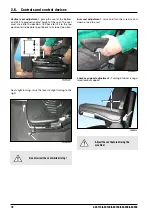
Страница 78: ...57 Secures protection of electric pump used for lifting and lowering of bonnet and driver s stand NOTE Replace the fuse with a genuine one of the same rate 50 A Driver s seat 58 Adjustable sprung equi...

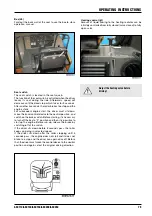
Страница 79: ...ssary Seat spring stiffness adjustment turn the catch to adjust stiffness according to driver s weight indicator 1 between 50 and 130 kg 110 266 lb in 10kg 22 lb increments Horizontal seat squab adjus...

Страница 80: ...he position You have to lift it to the top position first to be able to put it back to its lowest position Arm rest adjustment raise and turn the screw to cast down a raise the rest Adjust the seat be...

Страница 81: ...r another 5 seconds the roller brakes to a stop and the engine stalls For subsequent engine start the driver must sit down move the travel control device to the neutral position and switch on the brak...

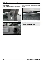
Страница 82: ...50 2 6 Controls and control devices Heating vents 62 Tilt the vents to adjust amount of fresh air swivel to adjust direction Front and rear windshields are blown with hot air to avoid dewing NOTE Ensu...

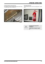
Страница 83: ...ntrol lever 63 Use the lever to control manual hydro generator of lifting and lowering the cabin and bonnet Fire extinguisher 64 For instructions how to use the fire extinguisher see the label Get fam...

Страница 84: ...ontrol devices Washer tank 65 The tank is used for supplying solution to two pumps of windshield washers for front and rear washer jets NOTE Fill the tank with anti freeze solution before winter Bottl...

Страница 85: ...F12 F13 F14 F15 Storage compartment 67 Compartment for driver s personal belongings Connector 70 Use this connector for warning beacon Engine fuses 74 Fuses F10 F12 7 5 A power supply engine electro...

Страница 86: ...signal lamp must go off after starting up the engine WARNING Do not start longer than 30 seconds Wait for 2 minutes before next starting Repeat starting procedure 3 times at most then detect the caus...

Страница 87: ...85 ASC110 ASC130 ASC150 ASC200 ASC250 OPERATING INSTRUCTIONS...

Страница 88: ...lectrically conducting parts of the machine risk of short circuit Do not lean over batteries beware of electrolyte burns Keep away sources of fire open flames lit cigarettes etc Do not test whether wi...

Страница 89: ...e sure that the area in front and in the back of the machine is free and that no persons are present in this area Turn off gear selector 2 to set the working gear mode Select appropriate range of work...

Страница 90: ...ace It is possible to activate selector 2 while the machine is under load rabbit symbol will light up Should towing power be insufficient turn the transport gear selector off 2 Do not drive across tra...

Страница 91: ...orking gear range Use pre selector 40 to turn on vibration amplitude Use selector 8 to adjust maximum engine speed The switch 15 must be switched off Start moving and use switch 6 to turn on vibration...

Страница 92: ...ion signal lamp 28 will go off Use control 1 to stop the machine signal lamps 23 and 24 will light up Brake the machine with a switch 4 Press button 15 to adjust idling speed Turn the ignition key to...

Страница 93: ...eutral position or is it impossible to shut down the engine by starter switch key Press button 5 the engine will stop and the machine as well NOTE Before restarting the engine turn the button 5 in the...

Страница 94: ...ector Clean the machine from dirt scraper and tyres Check the whole machine and repair defects arisen during the operation Check the tyre pressure Secure wheels and drum with scotch blocks Lock covers...

Страница 95: ...d Example of flashing error code Flashing code consists of three digits Example code 123 signal lamp Yellow lamp 19 will flash red lamp 18 will flash the code after 1 2 sec Number 1 red will flash onc...

Страница 96: ...or fails or the contact to the cell is broken the wheel will be unlocked automatically while driving after 5 seconds and will start turning The wheel will lock up again for five seconds after stopping...

Страница 97: ...95 ASC110 ASC130 ASC150 ASC200 ASC250 OPERATING INSTRUCTIONS 2 7 9 Blade Unlock the blade on both sides For locked secured blade For unlocked blade...

Страница 98: ...nd operation of the machine Start the engine Switch off the Idle switch 15 set maximum RPM 8 or those proportional to the subse quent output Switch off the gear selector 2 and choose a suitable range...

Страница 99: ...rame beam as related to the movable indicator with the blade 94 and remember this information This is then the basic position of the blade Return the controller pedal to 0 position and start driving T...

Страница 100: ...tion I blade moves down position II blade moves up position III blade is in floating position Volume of the shovelled material can be corrected by lowering the blade blade lever in I position or by li...

Страница 101: ...e left side under the driver s stand Take out the pump lever 2 Levers of lifting and lowering 3 Move the lever to A position lifting Insert the lever to the pump and lift the driver s stand Move the l...

Страница 102: ...hydro generator Lifting and lowering using electric hydraulic pump op tional Remove nuts of the driver s stand Connect electric system by turning the battery discon nector 1 Press and hold button 2 l...

Страница 103: ...e the manual hydro generator to perform lifting and lowe ring Open the cover 1 on the left side under the driver s stand Take out the pump lever 2 Driver s stand Remove nuts of the driver s stand Push...

Страница 104: ...r the driver s stand Screw the driver s stand in after lowering If the driver s stand is not screwed in properly the machine may overturn and cause lethal injuries Bonnet Push the sliding valve 3 on t...

Страница 105: ...ion slip control when driving up the transporting vehicle It is recom mended to underlay drum with rubber strips or wooden planks etc The vehicle transporting the roller must be braked for loading and...

Страница 106: ...dimensions of international railroad freight traffic The cabin and safety frame must be removed when transporting on these railroads BDZ Bulgarian Railways CH Greek Railways CFL National Company of L...

Страница 107: ...8 4 Loading the machine Use drive up ramps or crane to load the machine to a transporting vehicle The roller is equipped with lifting eyes for loading by crane Lock the joint against movements prior...

Страница 108: ...king pin Do not step under the hanging load Return the safety arm and blocks to default positions after loading is complete Observeappropriateregulationswhile loadingandunloadingthemachine Useappropri...

Страница 109: ...t dismantle cabin and ROPS frame Dismantling ROPS Hang the frame by lifting eyes Dismantle bolts and remove the frame Dismantling cabin Remove bolts 1 fastening the cabin to the platform Disconnect el...

Страница 110: ...he frame of drum Options Pin is also used for front towing lug on the crossbar of the front frame It is forbidden to use the machine for towing towed vehicles e g tanks compressors house trailers etc...

Страница 111: ...IONS 2 1 4 3 1 3 Releasing drum and wheels for ASC 110 150 Release all multi plate brakes to avoid slipping of drum and wheels Release hose 1 in clip 2 Disconnect hose 3 from tube 4 Connect hose 1 of...

Страница 112: ...ver on the left side under cabin Take out the lever 68 under the driver s stand Insert the lever 68 into the manual hydro generator and pump until the machine is unbraked for towing now Releasing brak...

Страница 113: ...e 1 from hose 3 in the quick coupling 2 Connect hose 3 back to tube 4 Fix hose 1 in clip 2 Turn the ignition key to I position and check signal lamp of brake 23 switched off NOTE During towing leakage...

Страница 114: ...enerator lever 63 to the hol der under the driver s stand WARNING During towing leakage may cause pressure in brakes decrease When towing check brakes for heating due to insufficient brake release To...

Страница 115: ...tance if the engine is running and the driving unit and steering are functional The drive on the towed roller must steer the roller in the dragging direction If the engine is stopped Avoid damagingino...

Страница 116: ...ing If it is necessary to compact at temperatures below 0 C 32 F dry soil can be compacted and stone aggregates or non frozen material must be compacted quickly before it will freeze Prepare the machi...

Страница 117: ...of temperature rise results in power output decrease of up to 4 at a constant humidity every 10 of relative humidity rise results in power output decrease of up to 2 at a constant tempera ture At high...

Страница 118: ...500 1640 3 1000 3281 6 1500 4921 10 2000 6562 15 2500 8202 21 3000 9843 28 If the engine produces black exhaust fumes in higher altitude contact a service organisation of the engine manufacturer that...

Страница 119: ...off both tyres and screw out inflation valves 1 and caps 2 Screw the filler gr 635 spare parts list to the cap opening 2 and insert the hose of filling device higher positioned container pump etc Star...

Страница 120: ...crew valves Warning The solution will squirt out at unscrewing Unscrew caps 2 Screw the filler into the opening see gr 635 Parts katalogue Rotate tyres so that fillers are at bottom positions Apply a...

Страница 121: ...tioner When retrofitting air condition unit it is necessary to keep sufficient distance between the oil cooler and air conditi oner condenser in order that air flow the machine cooling system is not a...

Страница 122: ...120 ASC110 ASC130 ASC150 ASC200 ASC250 N s e t o...

Страница 123: ...121 ASC110 ASC130 ASC150 ASC200 ASC250 OPERATING INSTRUCTIONS N s e t o...

Страница 124: ...122 ASC110 ASC130 ASC150 ASC200 ASC250...

Страница 125: ...123 ASC110 ASC130 ASC150 3 MAINTENANCE MANUAL ASC 110 ASC 130 and ASC 150 Cummins tier 2...

Страница 126: ...124 ASC110 ASC130 ASC150...

Страница 127: ...luids use recommended fills Operationsperformedwhiletheengine is running adjusting must be perfor med with another person present This personmusthaveimmediateaccessto the emergency stop and must be in...

Страница 128: ...original pro perly marked containers Avoid storing these materi als in unmarked bottles or other containers because of risk of possible substitutions Possible substitution of food and beverages is par...

Страница 129: ...machine are decisive Permitted oil according to API CH 4 SJ CI 4 All season SAE 15W 40 e g Valvoline Premium Blue NOTE Exceeding of the lower temperature limit does not dama ge the engine it may only...

Страница 130: ...T ANTIFREEZE SHELL Glycoshell AF 511 S TEXACO HAVOLINE Antifreeze Coolant AFC CASTROL ANTIFREEZE MB NOTE Do not use more than 50 of antifreeze in the coolant unless absolutely necessary Never use a ra...

Страница 131: ...of leak NOTE Water content condensation water in oil must not exceed the limit of 0 1 Operating fluid must be checked by taking samples in regular intervals see the chart When filling older machines w...

Страница 132: ...P Y H P E R A E G O P Y H L O R T S A C Y O P Y H Y O P Y H N O R V E H C R A E G L A S R E V I N U E T N A C I R B U L R A E G L A S R E V I N U E T N A C I R B U L F L E 8 F L E S N A R T 8 F L E S...

Страница 133: ...o b r a e G 7 0 x 2 8 2 x 2 t n i o j s g n i r a e b t n i o J r e d n i l y c g n i r e e t s d n a 6 2 3 r e t p a h c o t g n i d r o c c a e s a e r g c i t s a l P d e r i u q e r s a m e t s y...

Страница 134: ...132 ASC110 ASC130 ASC150 3 4 Lubrication and Maintenance Chart...

Страница 135: ...133 ASC110 ASC130 ASC150 MAINTENANCE MANUAL...

Страница 136: ...134 ASC110 ASC130 ASC150 3 5 Lubrication Chart...

Страница 137: ...gine which is a part of documentation supplied with the machine Disassembled or loose bolts plugs threaded connections of hydraulics etc should be tightened with torque according to tables in chapter...

Страница 138: ...e filler plug 2 through the oil filler Wait approx 1 min until the level is stable and check again NOTE The amount of oil between the dipstick marks is 0 95 litre 1 0 US Quart Refill the identical typ...

Страница 139: ...y cooling liquids containing the frost resistant agents on the identical basis according to chapter 3 2 3 Do not add additives eliminating untightness of the cooling system to the engine cooling liqui...

Страница 140: ...the oil level falls below the lower edge of the MIN oil level indicator the engine will automati cally stop and signal lamp 27 will light up NOTE In case of more extensive losses find the location of...

Страница 141: ...ondition of the ventilator Check the ventilator visually In case of any damage e g missing parts of the material cracks changes in shape etc replace the ventilator 3 6 6 Checking the engine inlet pipi...

Страница 142: ...he vacuum valve of the air cleaner Clean the exit slit and remove the trapped dust by pushing NOTE Collected dust is stored in the dust valve and automa tically emptied during the machine operation If...

Страница 143: ...p to the lower edge of the tank filler through the strainer NOTE The capacity of the fuel tank is 410 l 108 US gallons The capacity of full fuel tank is approximately 34 hours of operation of the mach...

Страница 144: ...s down by approx 25 mm 1 Let fuel drain until clean fuel starts to drain Then push the valve up and screw it in NOTE If you drained more than 6 cl 2 ozs of fuel refill fuel into the fuel filter accord...

Страница 145: ...go off Start driving the machine and test the emergency brake 5 and signal lights 23 Continuouslycheckdevicesandsignal lightsduringoperation Repairanyindicateddefectsimmedia tely Announce starting the...

Страница 146: ...tions of Maintenance 1 Every 100 Hours Every 100 Hours 3 6 11 Checking the tyre pressure Inflate the tyres 1 by pressured air through tyre valves 2 Check the pressure in cold tyres by air pressure met...

Страница 147: ...onto flat firm surface Stop the engine Prepare a suitable container with the capacity of ap proximately 20 l Dismantle the drain plug 1 and let oil drain Clean the area around the oil filter head Dis...

Страница 148: ...e filter and tighten firmly with hand Check the drain plug sealing replace it if damaged Check the engine sump thread and clean the contact area of the sealing Mount the plug back Tightening torque is...

Страница 149: ...he engine for 2 3 min Check tightness of drain plug and filter Stop the engine wait for approx 5 min until oil runs down to the engine sump Then check the level with oil dipstick NOTE Drain oil after...

Страница 150: ...er according to chapter 3 6 36 3 6 15 Checking batteries Place the roller onto flat firm surface Stop the engine and disconnect the electric system using the isolating master switch Clean the surface...

Страница 151: ...advice In case of ingestion of electrolyte drink maximum possible amount of milk water or mixture of magnesium oxide with water In case of staining your skin with elect rolyte take off your clothes an...

Страница 152: ...switch of the air cleaner Set engine speed to increased speed of approx 1500 rpm Dismantle the engine suction cover Shortly cover the inlet opening of the air cleaner on the engine bonnet After such...

Страница 153: ...the roller onto flat firm surface Stop the engine and disconnect electric system using the isolating master switch Remove the caps on the grease nipples Successively mount the grease nipple of pressu...

Страница 154: ...very 250 Hours or Once in 3 Months Every 250 Hours or Once in 3 Months Hydraulic cylinders of bonnet lifting upper pins 2x lower pins 2x Hydraulic cylinder of driver s post lifting lower pins 2x rear...

Страница 155: ...Hours or Once in 3 Months Every 250 Hours or Once in 3 Months Door hinges pins left right side Bonnet hinges pins pins 2 x Front pins of cabin attachment pins 2 x NOTE Use only recommended lubricatin...

Страница 156: ...n order that the plugs on the left side of the drum are in the position according to fig Clean the area around the checking plug 1 Unscrew the plug 1 and check the oil level The oil level must reach t...

Страница 157: ...reach the checking opening or slightly flow out Refill oil through the filling plug 2 if necessary Clean the plugs and mount again Drum gearbox Clean the area around the checking plug 1 Unscrew the p...

Страница 158: ...th 3 6 20 Engine fuel filter exchange Stop the engine Disconnect water separator sensor connector 1 dis mantle water separator sensor 2 from the filter and assembly it on new filter Clean the head of...

Страница 159: ...oke nor use open fire when working Collect leaking fuel Store used filters in a separate container and dispose of them 3 6 21 Checking cooling liquid Check the concentration of anti freeze agent in co...

Страница 160: ...dual Operations of Maintenance Every 500 Hours or Once in 6 Month Every 500 Hours or Once in 6 Month 3 6 22 Checking tightening bolts of wheel Check tightening bolts of wheel using a torque wrench Tig...

Страница 161: ...he groo ved pin Insert the grooved pin Cummins no 3824591 with 1 2 recess for hex key Using the key you can manually turn the engine Every 1000 Hours or Once a Year By slow turning the engine find the...

Страница 162: ...he remaining valves according to the figure Mount again the valve covers Mount the inlet air piping WARNING Check and adjust the valves when the engine is cooled down to below 60 C The order of cylind...

Страница 163: ...lley Stop the engine Lift the belt tensioning pulley using the lever and remove the belt Check visually the belt search for its damage Cracks perpendicular to the belt are not defects In case any leng...

Страница 164: ...Unscrew both plugs and clean them and drain oil fter draining drive away with the roller so that the plugs turn to the position Fill oil through the upper plug 2 until the level reaches the checking...

Страница 165: ...onhours Do not touch the gearbox and adjacent parts if they are hot Clean the area around plugs Put appropriate vessel under the drain plug 3 Unscrew all plugs 1 2 3 and let oil drain Mount the drain...

Страница 166: ...the condition of metal rubber mountings and bonding of metal with rubber Drum damping system left side Drum damping system right side Front metal rubber mountings driver s post Rear metal rubber mount...

Страница 167: ...ng dismantle the batteries and the tank cover 1 Check and clean the inside of the tank Insert a new sealing teflon strip between the cover and the tank and screw in the cover Mount the batteries NOTE...

Страница 168: ...r Every 2 Years Put appropriate vessel under the drain plug Unscrew all plugs and let oil drain Mount the drain plug after draining is finished Refill recommended oil to the edge of the checking openi...

Страница 169: ...heck the inside of the tank Carefully clean the bot tom and flush it with new oil if there are any impurities on the bottom Reassemble and wipe the O ring with clean oil NOTE For easier cleaning it is...

Страница 170: ...ng properly Filling the hydraulic circuit Use a filling device with the following parameters min pressure 6 MPa 870 PSI filtering property 3 to 10 m Open the cover on the right side under the cabin an...

Страница 171: ...me of hydraulic units You can order a filling device at the manufacturer of the machine or your dealer NOTE After filling the circuit check whether signal lamp doesn tshine NOTE Start the engine and r...

Страница 172: ...0 through 60 C 122 140 F Dismantle the filter container 2 using wrench 27 Take out the filter element 3 Carefully clean the filter container Clean the contact surface of the filtration block from the...

Страница 173: ...rainer of lifting and lowering of the bonnet and the driver s post NOTE Clean the strainer when exchanging hydraulic oil Unscrew bolts 1 take out the unit from the bottom of the tank Remove the suctio...

Страница 174: ...ystem by removing pressure plug 1 on the equaliser reservoir Do not dismantle the pressure plug be fore the temperature of cooling liquid fallslowerthanto50 C 122 C Bewa reofgushingofthecoolantandscal...

Страница 175: ...t the engine and wait until the temperature rea ches 80 C 175 F Check during your waiting for any leakage of cooling liquid Stop the engine Check the level on the indicator 2 If the level is low refil...

Страница 176: ...mm 1 16 in it is necessary to exchange the damper Check whether the rubber component 3 is not higher or lower above the level of metal parts 1 and 2 by more than 3 18 mm 1 8 in If the limit is exceed...

Страница 177: ...the engine and disconnect electric system Lift the bonnet to the limit position See Operating instructions chapter 2 7 10 Unscrew the wing nut 1 Carefully remove the cover with the main element 2 Mai...

Страница 178: ...the inside of the cleaner by pressure air dust might get into the engine inlet piping Replace both elements after 1 year of service at the leatest Replace the sealing nut with a new one when replacin...

Страница 179: ...ycombs In case of contamination of the radiator by oil products use a cleaning agent and proceed accor ding to the manufacturer s instructions Find the cause of contamination Followenvironmentalstanda...

Страница 180: ...leaning regularly at least once in a week When working in cohesive soils cement and lime stabilisation s the overall cleaning must be per formed daily NOTE Blind all openings into which the cleaning a...

Страница 181: ...afety precautions Fuelpressureinthehigh pressurema nifold is high and may cause skin and other serious injury Venting must not be performed on the hot engine as fuel may flow on the hot exhaust manifo...

Страница 182: ...in the range of oval openings of the holders 2 due to the wear of the scrapers dismantle the scraper 3 and move it closer to the drum by one hole Scrapers for the taper foot drum Loosen bolts 1 and mo...

Страница 183: ...M G N I N E T H G I T s w e r c s e h t r o F S 5 8 5 s w e r c s e h t r o F G 8 8 8 s w e r c s e h t r o F K 0 1 9 0 1 m r o W m N t f b l m N t f b l m N t f b l 4 M 2 1 3 2 4 3 5 M 4 3 6 4 8 6 6...

Страница 184: ...5 1 x 4 1 M 8 8 3 0 3 5 4 8 2 2 2 3 3 9 1 5 1 x 6 1 M 8 5 4 8 3 2 5 3 3 8 2 8 3 0 1 2 2 5 1 x 8 1 M 0 1 1 5 3 4 8 5 8 3 2 3 3 4 2 1 4 2 5 1 x 0 2 M 2 1 8 5 0 5 5 6 3 4 7 3 8 4 7 2 5 1 x 2 2 M 4 1 4 7...

Страница 185: ...1 x 6 1 M 0 6 4 4 5 1 x 8 1 M 0 6 4 4 5 1 x 0 2 M 0 4 1 3 0 1 5 1 x 2 2 M 0 4 1 3 0 1 5 1 x 6 2 M 0 2 2 2 6 1 5 1 x 7 2 M 0 5 2 4 8 1 5 1 x 3 3 M 0 0 4 5 9 2 5 1 x 2 4 M 0 0 6 3 4 4 5 1 x 8 4 M 0 0 8...

Страница 186: ...184 ASC110 ASC130 ASC150 3 6 Individual Operations of Maintenance...

Страница 187: ...ructions given in the operation and maintenance manual for the machine and engine If you cannot identify the cause contact a service department of an authorised dealer or the manufacturer NOTE Trouble...

Страница 188: ...Switch of warning lights optional S7 Change over switch of direction lights optional S8 Switch of safety beacon optional S9 Push button of horn S11 Push button of emergency brake S12 Switch of back up...

Страница 189: ...187 ASC110 ASC130 ASC150 MAINTENANCE MANUAL...

Страница 190: ...188 ASC110 ASC130 ASC150 3 8 Appendixes...

Страница 191: ...189 ASC110 ASC130 ASC150 MAINTENANCE MANUAL...

Страница 192: ...EMMEGI 18 One way valve HYTOS 20 Thermoregulator 21 Check point STAUFF 22 Quick release coupling male FASTER 23 Quick release coupling female FASTER 24 Quick release coupling male FASTER 25 Temperatur...

Страница 193: ...191 ASC110 ASC130 ASC150 MAINTENANCE MANUAL...

Страница 194: ...ne way valve HYTOS 20 Thermoregulator 21 Check point STAUFF 22 Quick release coupling male FASTER 23 Quick release coupling female FASTER 24 Quick release coupling male FASTER 25 Temperature sensor 26...

Страница 195: ...193 ASC110 ASC130 ASC150 MAINTENANCE MANUAL...

Страница 196: ...194 ASC110 ASC130 ASC150 3 8 Appendixes N s e t o...

Страница 197: ...195 ASC110 ASC130 ASC150 MAINTENANCE MANUAL N s e t o...

Страница 198: ...N s e t o...

Отзывы: