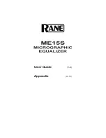
Fit DIP PCB to top side of Inductor PCB
(using 4mm spacer PCBs)
Assembly Tip:
Use the faceplate to help align
the switch PCBs before soldering
all the pins.
Use the 4mm spacer tool PCBs
to set the height of the DIP PCB
above the Inductor PCB.
Solder 1 pin of each header then
remove the spacer tool and use
the faceplate to check the
alignment.
Содержание ezMEQ-500
Страница 1: ...ezMEQ 500 Passive Midrange Equalizer Assembly manual Colourbook Issue 2...
Страница 5: ...Diodes D1 D2 D3 1N4007 3...
Страница 6: ...R28 10R 1 R27 12R 1 R10 R24 75R 2 R43 270R 1 Resistors...
Страница 7: ...R15 R18 470R 2 R38 510R 1 R6 R14 620R 2 R39 1k0 1 Resistors...
Страница 8: ...R11 1k2 1 R13 1k5 1 R9 2k2 1 R36 R41 3k0 2 Resistors...
Страница 9: ...R19 3k3 1 R33 5k6 1 R35 7k5 1 R7 R16 R30 10k 3 Resistors...
Страница 10: ...R8 R25 18k 2 R32 22k 1 R3 R4 R5 33k 3 R17 R20 56k 2 Resistors...
Страница 11: ...R29 100k 1 R12 120k 1 R37 180k 1 R40 220k 1 R31 1M0 1 Resistors R23 OMITTED...
Страница 12: ...C17 100nF 1 C9 C48 C49 220pF 3 C50 47pF 1 C12 330pF 1 Ceramic Capacitors C3 OMITTED...
Страница 13: ...EMC Filters F1 F2 Ferrite Bead 2 CL 1 CL2 100pF C L Network 2...
Страница 14: ...C43 C46 2n2F 2 C10 C42 4n7F 2 C7 470pF 1 C41 3n3F 1 Film Capacitors...
Страница 15: ...C29 C30 C32 C45 15nF 4 C27 47nF 1 C13 C44 10nF 2 C21 C23 C38 C47 33nF 4 Film Capacitors...
Страница 16: ...C34 C35 100nF 2 C19 C33 220nF 2 C22 C25 C36 150nF 3 Film Capacitors C26 82nF 1...
Страница 20: ...Trimmers and Relay R21 R42 500R Top Adjust Trimmer 2 RL1 24 Volt DPCO relay 1 R22 5k Top Adjust Trimmer 1...
Страница 22: ...Large Capacitors C2 C4 C8 470uF 35v 3 Positive terminals towards left...
Страница 46: ......
Страница 47: ......