background image

LoRa Node


37 


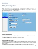
Click 

Restore

 button to restore the device settings to a certain backup copy, or quickly duplicate a device’s 

configuration file to the other devices with the same configuration for  a certain application. In such case, 

ensure to set the unique Device ID for separate devices. 
 

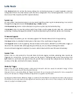
System Log 

For some device maintenance purpose, you may need to get the system log for troubleshooting. You can do it 

through the configuration tool, click 

Download Log

 or 

Delete

 button. 

Click 

Download Log

 button to store the System Log into a log file (.txt) for troubleshooting.  

Click 

Delete

 button to erase the existing system logs. Please use the delete function with care, all the device 

system log, including data log will be erased. If required, download log first and then delete out-of-date log. 
 

Firmware Upgrade 

If new firmware is available, you can manually upgrade it for feature enhancement or bug resolving. 
Click 

Open

 button to indentify the file location / file name of the new firmware image (.bin).  

Click 

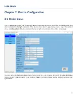
Upgrade 

button to start upgrading the new firmware to the device. DO NOT turn off the Data Logger, or 

disconnect the console cable while upgrading new firmware, it is very likely to damage the device. 
Once the Firmware Upgrade completed, the device will be reboot with the new firmware immediately. 
 

System Time 

System time is a vital element for the LoRa Node. Both data logging and data uploading tasks need to be 

triggered at a certain time. You have to make sure the device is configured with correct time setting. Click 

Sync.

 button to synchronize the system time with your PC that is running the configuration tool. Besides, you 

can also set the date and time for the device manually. 
 

Wake-Up Trigger 

Most of the time, the IOT400 operates under sleep mode with ultra low power consumption design. At that 

time, no one can wake it up till the schedule time out. 

However, there is a manually Wake-Up Trigger mechanism for you to wake up the device for some unexpected 

reason, for example, to change software configuration or upgrade new firmware. 


By default the Reed Switch Wake-Up Trigger is enabled. The Reed Switch is located at the lower-left corner of 

the IOT400. You can just take a small magnet and touch the lower-left corner of the enclosure, the IOT400 will 

detect it and get into WakeUp state.  


Содержание LoRa IOT400-DL3B1

Страница 1: ...LPWA LoRa LoRa Node IOT400 DL3B1 User Manual...

Страница 2: ...ation 10 1 6 1 Open the Top Cover 10 1 6 2 Install Battery 12 1 6 3 Connecting to External Devices 14 1 6 4 Connecting Console Port for PC Configuration Tool 21 1 6 5 Power On the IOT400 23 1 6 6 Setu...

Страница 3: ...ltra low power consumption which allows it to operate on a single battery for years 1 Main Features Simple device with various interfaces AI DI RS485 for IIoT field data acquisition Transfer of field...

Страница 4: ...e 2pcs 4 AI Jumper 3pcs 5 Water Dust proof Stopper 3pcs 1 2 2 Optional Accessories Optional parts these parts are sold separately Items Description Contents Comments 1 USB to Serial Console Cable Used...

Страница 5: ...LoRa Node 5 1 3 Hardware Configuration Front View M16 Water Dust proof Connectors with two hole cable gland inserted...

Страница 6: ...ion LED Icon Indication LED Color Description LED Device Status Blue Red Steady OFF Device is powered off Blue Steady ON Device is boot up Red Flash Battery Low Blue and Red Steady ON Device is in Rec...

Страница 7: ...h 4 x or later for wireless console 1 5 2 WARNING Only use the Battery that comes with the package or the external DC Power Supply that complies to device spec Using a different voltage rating power a...

Страница 8: ...and receiver Connect the equipment into an outlet on a circuit different from that to which the receiver is connected Consult the dealer or an experienced radio TV technician for help FCC Caution Any...

Страница 9: ...t from the following URL http www amit com tw products doc 3 RF Exposure Statements The antenna of the product under normal use condition is at least 20 cm away from the body of user 4 Unit Mounting N...

Страница 10: ...battery or external 5V 12V DC power This section describes how to install and configure the hardware 1 6 1 Open the Top Cover The IOT400 series is design for universal data logging use There are vari...

Страница 11: ...the required configuration and need to Power Up the device 3 The RESET button provides user with a quick way to reboot the device S1 Power Switch ON OFF J6 Power Source Jumper S2 RESET Button S3 DIP s...

Страница 12: ...LoRa Node 12 1 6 2 Install Battery Step 1 Insert the two cable ties and go through the battery stands Step 2 Load the battery over the stands as the illustrated and pull tightly for each cable tie...

Страница 13: ...cause explosion combustion internal acid leakage 2 The Li SOCL2 battery is an one time battery DO NOT re charge crush disassemble the battery in any situation 3 Discharged battery is a hazardous waste...

Страница 14: ...devices As indicated in the I O pinout sheet you can easily find out the pin location and connect to your devices with appropriate conductive cables However there are only two dual hole M16 water dust...

Страница 15: ...ls b Remove the external part of the M16 connector c Run the cable through the external parts as indicated below Step 2 a Place the tinned terminal over the connector b Use a flathead screwdriver and...

Страница 16: ...operly 2 However if you intend to run more than two cables through the M16 connector or IP65 is not so critical for the installation you can decide not to put the cable glands and skip step 1b 1d for...

Страница 17: ...for each AI port AI1 AI2 AI3 Without Jumper 0 10V Voltage mode factory default With Jumper 4 20mA Current mode You have to put the Jumper manually Pinout Definition CON5 Pin1 Pin2 Pin3 Pin4 Pin5 Pin6...

Страница 18: ...ts either Pulse counter mode or just a Dry contact Since the IOT400 can not detect what kind of device is connected to not only hardware configuration CON5 is required but also software configuration...

Страница 19: ...unexpected reason for example to change software configuration or upgrade new firmware there is a manually wake up mechanism for such kind of maintenance situation There is an internal magnetic Reed S...

Страница 20: ...source to the IOT400 directly if there is available DC power source at the installation site Pinout Definition CON2 Pin1 Pin2 Pin3 Pin4 Pin5 Pin6 Pin7 Pin8 GND VDC 5 12V VDC 5 12V GND RS485 D A RS485...

Страница 21: ...rt for device configuration You have to connect either USB to Serial console cable or Bluetooth module4 to the Console Port at CON1 as illustrated below Pinout Definition CON1 USB to Serial and Blueto...

Страница 22: ...LoRa Node 22 Console port CON1 with USB to Serial Console cable or Bluetooth Module inserted S3 1 OFF for wired configuration via Console cable S3 1 ON for wireless configuration via Bluetooth Module...

Страница 23: ...attery Power Battery power cable is plugged onto the Power Socket CON3 and Power Source Jumper J6 is placed at the left side BAT For External DC Power External DC power cable is inserted into the exte...

Страница 24: ...LED2 for 1 2 seconds After a while LED1 and LED2 will turn to OFF state and then after booting up you will see the LED2 with BLUE light is ON steady Power OFF Boot up Note If the IOT400 is powered wi...

Страница 25: ...OT400 Configuration Tool you will see the login dialog Click the drop down menu next to the Serial Port Choose the COM port that is bound to the IOT400 console port and then click Connect button Note...

Страница 26: ...a list of menu items appears on the left side under the Login Tab Now you already logged in to the IOT400 console and you can proceed with the required software configuration steps one by one Refer t...

Страница 27: ...lowing actions for it 1 Power Off the IOT400 and remove the console cable Bluetooth Module 2 Mount the IOT400 base enclosure on the planned location 3 Make sure all the wiring cables are running in po...

Страница 28: ...ght hand side If the device status doesn t appear or you want to get the updated status click Status Refresh button located at the lower right corner to refresh the status immediately You can see the...

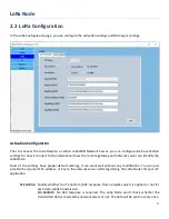
Страница 29: ...r can identify the LoRa Node Most of the settings have proper default settings it can work well without any modification You can just provide the required EUI address or Key to the network server whil...

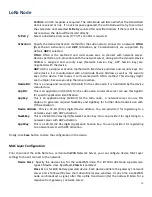
Страница 30: ...hardcoded by the device manufacture AppEUI This is an application ID 64 bit for the LoRa node A network server can use this AppEUI for specific application identification AppKey This is an applicatio...

Страница 31: ...ult 600 seconds is configured It means the node will transmit the status of connected sensor meters on every 600 seconds time interval Finally click Save button to store the configuration in the devic...

Страница 32: ...ame for identification and the Mode Dry Contact or Pulse Counter for each connected port And then click Enable check boxes for those connected ports If Pulse Counter mode is selected some additional f...

Страница 33: ...to store the I O settings the following dialog will appear for you to double confirm the settings of Analog Input type that the H W configuration and S W configuration are consistent After you confirm...

Страница 34: ...p Bits and Parity settings Interface By default the interface is disabled You can enable it and set the interface parameter to comply with the devices to be connected Baud Rate Select the appropriate...

Страница 35: ...device Slave ID Specify a unique ID for the slave device It can be 1 247 Function Code Specify a certain read function for the Data Logger to issue and record the responses from slave device It can b...

Страница 36: ...ation you may need to reboot the Data Logger or reset the device configuration to its default value Click Reboot or Reset button and wait a while for the device to reboot Configuration Backup Restore...

Страница 37: ...re to the device DO NOT turn off the Data Logger or disconnect the console cable while upgrading new firmware it is very likely to damage the device Once the Firmware Upgrade completed the device will...

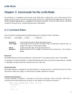
Страница 38: ...Length of Command Total Length Data Data accompanied data bytes for the issued command Checksum Checksum byte for the complete command stream Command Total Length Data Direction The MSB of the Comman...

Страница 39: ...LoRa Node 39 for i 0 i len i ret buf i return ret...

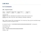
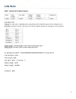
Страница 40: ...ports to network server Sequence DI 1 DI 2 AI 1 AI 2 AI 3 Modbus 1 Modbus 2 Modbus 3 Note 1 There is maximum limit on the payload size This command may not be used for some Modbus device configuration...

Страница 41: ...fier for each input port Only those enabled input ports will appear in the payload DI 1 0x10 DI 2 0x11 AI 1 0x30 AI 2 0x31 AI 3 0x32 Modbus 1 0x50 Modbus 2 0x51 Modbus 3 0x52 Data i Length the data le...

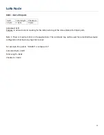
Страница 42: ...er is asking for the LoRa node to get the status data of all input ports Note 1 There is maximum limit on the payload size This command may not be used for some Modbus device configuration that has ma...

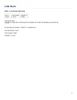
Страница 43: ...70 Total length Checksum 1 byte 1 byte 1 byte Command 0x70 Purpose A LoRa node is alerting to the network server with low battery power warning For example the packet 700272 is composed of Command byt...

Отзывы: