32 Amico Corporation
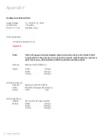
Appendix D
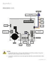
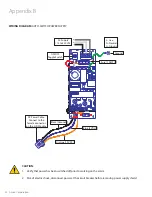
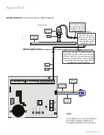
WIRING DIAGRAM:
LCD DISPLAY MODULE - LOCAL SENSOR
AC Supply
115 to 220 V
AC
DC P
ower Cable
:
Connect to
Annunciator Module
G
N
L
L - Live
N - Neutral
G - Ground
Fuse (1 AMPw)
Ground
To
ggle S
wit
ch
COM
B4
et
u
M /
tc
el
e
S
N
W
O
D
eg
na
h
C
P
U
eg
na
h
C
p
U -
te
S
B3
B2
B1
+12V
NO
NC
GRND
Reset
Button
S 8
S 7
S 6
S 5
S 4
S 3
S 2
S 1
OXYGEN
# 22 Gauge twisted
pair shielded cable
6”-8” [0.1m-0.2m] supplied
CAUTION:
To protect from static electricity,
ensure to discharge body static before
installing the Medical Gas Alarm and
sensors
NOTE:
Do not ground the shield drain wire at
sensor or inside alarm panel back box
Sensor
Module
6" - 8" [0.1m - 0.2 m]
#22 gauge stranded,
shielded twisted pair
cable supplied
Black
Red
Orange
(15 VDC)
Blue
(5 VDC)
Black
(Ground)

