29
www.amico.com
COM
B4
et
u
M /
tc
ele
S
N
W
O
D
eg
na
h
C
P
U
eg
na
h
C
p
U -
te
S
B3
B2
B1
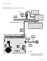
+12V
NO
NC
GRND
Reset
Button
Mute Button
(located on reverse side of board)
LCD Cable
Connector
SD Card
Four Push
Buttons
12V DC
Output
LCD Power
Dry Contacts
(to Building Management
System)
Buzzer
DC
Connector
Buzzer
Jumper
Ethernet
Port
S 8
S 7
S 6
S 5
S 4
S 3
S 2
S 1
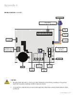
Appendix A
WIRING DIAGRAM:
LCD BOARD
CAUTION:
1. Keep the shield drain wires as short as possible and taped to prevent from grounding, so they cannot
touch the front panel circuit board when front panel is closed.
2. To protect from static electricity, ensure to discharge body static before installing the Medical Gas Alarm
and Sensors.
DC Connector
LCD Power
Mute Button
(located on reverse side of board)
Dry-Contacts
(Building
Management System)
Four Push
Buttons
12V DC
Output
LCD Cable
Connector
SD Memory Card
Slot (memory card
not provided)
Buzzer
Buzzer
Jumper
Ethernet
Port
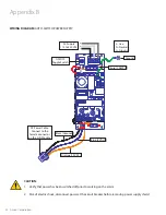
Orange
(15 VDC)
Blue
(5 VDC)
Black
(Ground)


