


AMG Systems Ltd. reserves the right to make changes to this
document without notice. The information herein is believed to
be accurate. No responsibility is assumed by AMG for its use.
Page 7 of 8
AMG5918 Instruction Sheet D22155-
00.doc
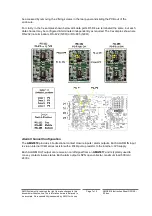
be accessed by removing the 2 fixing screws in the rear panel and sliding the PCB out of the
enclosure.
For clarity, in the 3 examples shown below all 4 data ports D1-D4 are terminated the same, but each
data channel may be configured & terminated independently as required. The 3 examples shown are
RS-232 (no termination), RS-422 (120Ω) or RS-485 (120Ω).
Alarm Channel Configuration
The
AMG5918
provides 4 bi-directional contact closure inputs / alarm outputs. Each ALARM IN input
is via an internal 10kΩ series resistor with a 47kΩ pull-up resistor to the in3V3 supply.
Each ALARM OUT output can receive an on/off signal from an
AMG5917
and is typically used to
convey contact closure status. Each alarm output is NPN open collector, maximum load 500mA /
24Vdc.


