AMG Systems AMG5918 Скачать руководство пользователя страница 3

AMG Systems Ltd. reserves the right to make changes to this
document without notice. The information herein is believed to
be accurate. No responsibility is assumed by AMG for its use.

Page 3 of 8

AMG5918 Instruction Sheet D22155-
00.doc

Introduction

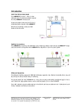
Unit Functional Schematic

The

AMG5918

receives 1 video, 4 data

channels and 4 bi-directional alarm signals
from the

AMG5917

transmit unit.

It also transmits 4 data channels and 4 bi-
directional alarm signals to the

AMG5917

.

Ethernet connectivity is also provided
between the two units.

Optical Connection

The

AMG5918

connections are illustrated in the following example which shows an

AMG5917

single

channel transmit unit together with a

AMG5918

configured as a point to point system.

Ethernet Operation

The Ethernet interface supports 100Mbit/s full duplex operation only. Data is transmitted from one port
the other port with minimum delay or buffering.

The port implements "Auto MDI/MDIX" i.e. it may be connected with either a straight-though or cross-
over cable to an appropriate device such as external switch, PC or other DCE/DTE.

Two LED indicators are provided adjacent to the RJ-45 port: Green indicates Link / Data transfer and
Yellow indicates no Ethernet connection.

Содержание AMG5918

Страница 1: ...s plus Ethernet for a Singlemode Fibre Link The AMG5918 is a standalone one channel video receive unit designed to receive 1 video signal and transmit and receive 4 data signals plus 4 bi directional...

Страница 2: ...ion 3 Connections 4 Video Output Connection 4 Optical Connection Singlemode 4 Power Connection 4 Data and Alarm Channel Connections 4 Ethernet Connection 4 Front Panel Indicators 5 Power LED 5 Low Spe...

Страница 3: ...between the two units Optical Connection The AMG5918 connections are illustrated in the following example which shows an AMG5917 single channel transmit unit together with a AMG5918 configured as a p...

Страница 4: ...oenix 1803578 Supply Voltage 12 to 15 Volts DC Maximum Power 2 5 Watts Data and Alarm Channel Connections No of Data Channels 4 No of Alarms 4 Connectors Removable 5 pin 3 5mm Spring Terminal Connecto...

Страница 5: ...RS232 Green logic zero V present on input IN Red logic transitions present on input IN Off logic one V present on input IN IN corresponds to the data signals being transmitted onto the optical fibre...

Страница 6: ...00mV positive or negative will be detected as a logic 1 or logic 0 respectively It is important therefore to terminate the RS 485 bus or the RS 422 input bus using 120 if a pre bias is present on the...

Страница 7: ...ports D1 D4 are terminated the same but each data channel may be configured terminated independently as required The 3 examples shown are RS 232 no termination RS 422 120 or RS 485 120 Alarm Channel C...

Страница 8: ...et and is then held firmly in position Safety AMG Optical Fibre Products use Class 1 laser systems in accordance with EN 60825 2 2000 It is always advisable to follow good practice when working with o...

Отзывы: