


AMG Systems Ltd. reserves the right to make changes to this
document without notice. The information herein is believed to
be accurate. No responsibility is assumed by AMG for its use.
Page 4 of 8
AMG5904 Instruction Sheet D22107-
00.doc
Connections
Optical Connection Singlemode
Optical Fibre ........................................Singlemode
Connector ............................................SC/PC
Primary Optical Launch Power ............-10dBm
Transmit Wavelength...........................1550nm
Primary Optical Sensitivity...................-30dBm
Receive Wavelength............................1310nm
Minimum Optical Dynamic Range .......20dB.
Power Connection
Connector Type ...................................Removable 2-pin, 3.81mm, Screw Terminal
Connector Partno.................................Phoenix 1803578
Supply Voltage.....................................+12 to +15 Volts DC
Maximum Power ..................................2.5 Watts
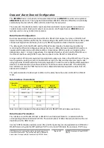
Data and Alarm Channel Connections
No. of Data Channels ..........................2
No. of Alarms .......................................8
Connectors ..........................................Removable 5-pin, 3.5mm, Spring Terminal
Connector Partnos...............................Phoenix 1952296
Data Interfaces ....................................RS-232 / 422 / 485. Selected by external slide switches D1-D2
RS-232 – Switch Position - Top
RS-422 – Switch Position - Middle
RS-485 – Switch Position - Bottom
Internal 120Ω termination resistors may be applied to RS-422 or RS-485 inputs as required by internal
DIL switches inside the enclosure. *See appropriate section on how to remove the case for access to
the DIL switches.
Alarm inputs.........................................Input is via a series 10k resister with 47kΩ pull-up to +3V3.
Alarm outputs.......................................Output is NPN open collector, maximum load 500mA @ 24Vdc
.
Ethernet Connection
Ethernet Data Connector ....................RJ45
Interface...............................................Auto-negotiation up to 100BASE-TX full duplex
Ethernet Data Rate ..............................Maximum 100Mb/s total Ethernet traffic on fibre