


AMG Systems Ltd. reserves the right to make changes to this
document without notice. The information herein is believed to
be accurate. No responsibility is assumed by AMG for its use.
Page 2 of 8
AMG5904 Instruction Sheet D22107-
00.doc
Contents
Introduction
3
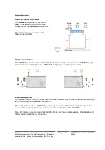
Unit Functional Schematic.................................................................................................................. 3
Optical Connection ............................................................................................................................. 3
Ethernet Operation ............................................................................................................................. 3
Connections
4
Optical Connection Singlemode ......................................................................................................... 4
Power Connection .............................................................................................................................. 4
Data and Alarm Channel Connections ............................................................................................... 4
Ethernet Connection........................................................................................................................... 4
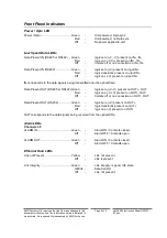
Front Panel Indicators
5
Power / Opto LED............................................................................................................................... 5
Low Speed Data LEDs ....................................................................................................................... 5
Alarm LEDs......................................................................................................................................... 5
Ethernet Data LEDs............................................................................................................................ 5
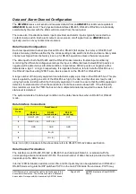
Data and Alarm Channel Configuration
6
Data Channel Configuration ............................................................................................................... 6
Data Interface Connections ................................................................................................................ 6
Data Channel Termination.................................................................................................................. 6
Alarm Channel Configuration ............................................................................................................. 7
Alarm Interface Connections .............................................................................................................. 8
Physical Information
8
Dimensions ......................................................................................................................................... 8
Mounting Details ................................................................................................................................. 8
Safety
8
Maintenance and Repair
8