


AMG Systems Ltd. reserves the right to make changes to this document without
notice. The information herein is believed to be accurate. No responsibility is
assumed by AMG for its use.
Page 2 of 9
AMG2783A-1-DR-
CWDMn,m -SF Instruction
Sheet D15185-00
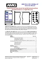
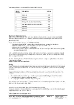
Introduction
Unit Functional Schematic
The unit transmits optically on two CWDM (Coarse
Wavelength Division Multiplexing) wavelengths,
transmitting in opposite directions onto a singe optical fibre.
The primary optical channel (transmission wavelength
indicated by
n) transmits in the clockwise direction and
the secondary channel (transmission wavelength indicated
by
m) transmits in the anti-clockwise direction. Thus a
CWDM1, 2 unit would have a primary optical channel on
CWDM wavelength 1 (
1) and a secondary channel on
CWDM wavelength 2 (
2).
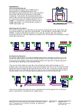
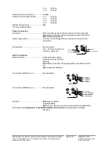
Optical System Connection
The units are designed to be connected in a ring. Up to 32 video channels can be connected on the
same dual redundant ring comprising of 8off CWDM1, 2, 8off CWDM3, 4, 8off CWDM5, 6 and 8off
CWDM7, 8. Each wavelength pair equipment is set, although using the same fibre operates
independently from the other wavelength pair equipment sets. The schematic below illustrates a single
wavelength equipment set.
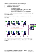
Dual Redundant Operation
The primary optical channel, normally transmitting optical signals clockwise around the ring, carries
the video and data signals during normal no break operation. The secondary optical channel is not
used to carry active signals in this normal operating situation but only serves to repeat (regenerate
and re-time) any optical signal received at each node.
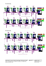
In the event of a fibre break, the units either side of that break detect what has happened. The
example shown in the schematic below shows a break between cameras 1 and 2. The video and data
signals that would normally be transmitted directly from unit 2 to unit 1 on the primary optical channel
will now be routed in the opposite direction from unit 2 to unit 1 on the secondary channel via each of
the other nodes in the ring. The signal being regenerated at each node it passes through.
In the case of multiple fibre breaks the receiver will still drop off all video signals from, and transmit
data to, nodes that are not isolated by the multiple breaks.
1
2
3
8
1
3
8
2
2783A-1-DR-CWDM1/2-SF
AMG
PRIMARY OPT O SYNC
TX
O O
RX
SECONDARY OPT O SYNC
TX
O O
RX
VIDEO PRESENT
CH1
O
O
RX
CH1
O
O
RX
DATAPRESENT
-- --- --- ---- --- --- ---- ---
1 CH VIDEO INSERT
+
DATA TX/RX
POWER
O
POWER
O
2783A-1-DR-CWDM1/2-SF
AMG
PRIMARY OPT O SYNC
TX
O
O
RX
SECONDARY OPT O SYNC
TX
O
O
RX
VIDEO PRESENT
CH1
O
O
RX
CH1
O
O
RX
DATAPRESENT
-- --- --- ---- --- --- ---- ---
1 CH VIDEO INSERT
+
DATA TX/RX
POWER
O
POWER
O
2783A-1-DR-CWDM1/2-SF
AMG
PRIMARY OPT O SYNC
TX
O
O
RX
SECONDARY OPT O SYNC
TX
O
O
RX
VIDEO PRESENT
CH1
O
O
RX
CH1
O
O
RX
DATA
PRESENT
-- --- --- ---- --- --- ---- ---
1 CH VIDEO INSERT
+
DATA TX/RX
POWER
O
POWER
O
2783A-1-DR-CWDM1/2-SF
AMG
PRIMARY OPT O SYNC
TX
O O
RX
SECONDARY OPT O SYNC
TX
O O
RX
VIDEO PRESENT
CH1
O
O
RX
CH1
O
O
RX
DATAPRESENT
-- --- --- ---- --- --- ---- ---
1 CH VIDEO INSERT
+
DATA TX/RX
POWER
O
POWER
O
2784-1-DR-CWDM1/2-SF
AMG
PRIMAR Y OPTO SYNC
TX
O
O
RX
SECONDARY OPTO SYNC
TX
O
O
RX
VIDEO PRESENT
CH1
O
O
CH2
CH3
O
O
CH4
CH1
O O
RX
DATA
PRESENT
-- --- ---- ---- --- --- ---- --
8 CH VIDEO RX
+
DATA TX/RX
PO WER
O
PO WER
O
VIDEO PRESENT
CH5
O
O
CH6
CH7
O
O
CH8
1
2
3
8
1
3
8
2
2783A-1-DR-CWDM1/2-SF
AMG
PRIMARY OPT O SYNC
TX
O
O
RX
SECONDARY OPT O SYNC
TX
O
O
RX
VIDEO PRESENT
CH1
O
O
RX
CH1
O
O
RX
DATA
PRESENT
-- --- --- ---- --- --- ---- ---
1 CH VIDEO INSERT
+
DATA TX/RX
POWER
O
POWER
O
2783A-1-DR-CWDM1/2-SF
AMG
PRIMARY OPT O SYNC
TX
O
O
RX
SECONDARY OPT O SYNC
TX
O
O
RX
VIDEO PRESENT
CH1
O
O
RX
CH1
O
O
RX
DATAPRESENT
-- --- --- ---- --- --- ---- ---
1 CH VIDEO INSERT
+
DATA TX/RX
POWER
O
POWER
O
2783A-1-DR-CWDM1/2-SF
AMG
PRIMARY OPT O SYNC
TX
O
O
RX
SECONDARY OPT O SYNC
TX
O
O
RX
VIDEO PRESENT
CH1
O
O
RX
CH1
O
O
RX
DATAPRESENT
-- --- --- ---- --- --- ---- ---
1 CH VIDEO INSERT
+
DATA TX/RX
POWER
O
POWER
O
2783A-1-DR-CWDM1/2-SF
AMG
PRIMARY OPT O SYNC
TX
O
O
RX
SECONDARY OPT O SYNC
TX
O
O
RX
VIDEO PRESENT
CH1
O
O
RX
CH1
O
O
RX
DATA
PRESENT
-- --- --- ---- --- --- ---- ---
1 CH VIDEO INSERT
+
DATA TX/RX
POWER
O
POWER
O
2784-1-DR-CWDM1/2-SF
AMG
PRIMAR Y OPTO SYNC
TX
O
O
RX
SECONDARY OPTO SYNC
TX
O O
RX
VIDEO PRESENT
CH1
O
O
CH2
CH3
O
O
CH4
CH1
O
O
RX
DATAPRESENT
-- --- ---- ---- --- --- ---- --
8 CH VIDEO RX
+
DATA TX/RX
PO WER
O
PO WER
O
VIDEO PRESENT
CH5
O O
CH6
CH7
O O
CH8
2783A-1--DR-CWDMn,m-SF
2700 optics (Primary)
TX
RX
2700 optics
(Secondary)
RX
TX
Primary and Secondary
Route on the Same Fibre
n
m
m
n
1 to
8 without
n and
m
1 Video Input
1 Data I/O
4dB Max Through Loss
1 to
8
OPTO OUT
OPTO IN
Primary Signal Direction
Secondary Signal Direction


