Electrical Circuit Diagram
eFutureSafe
Page 35 of 40
10
Electrical Circuit Diagram
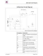
Figure 13: Electrical Circuit Diagram
Designation Description
F1
Fuse 10 A – Signal 30 (control unit power
supply)
F2
Fuse 1 A – Signal 15 (ignition)
G1
12 V starter battery
S1
Toggle switch (ON/OFF) in the dash-
board
L1
Indicator lamp in the dashboard
M1
Electric motor in the eFutureSafe
CB1 Control
unit
KS1
Contact switch in the eFutureSafe
X1
Plug-in connection to the control unit (7-
pole)
X2
Plug-in connection to the control unit (2-
pole)
black
black
red
red
Fuse
1 A
Fuse
10 A
CB1 - Control Unit
Dashboard
Con
necti
on
termin
als
not
used
Starter
battery
12 V
Содержание eFutureSafe
Страница 1: ...pillar Operating Instructions eFutureSafe Automatic Head Backrest www amfbrunsamerica com...
Страница 2: ......
Страница 38: ......
Страница 39: ......

