8
Manual Part No. 502923 Issue 3
5.0: Mechanical Installation
5.0: Mechanical Installation
5.4: Tip Adjustment
The Mini Probe Tip height can be adjusted over a
0.5 mm range (± 0.25 mm from the factory set position
-approximately ±½ turn).
To adjust tip
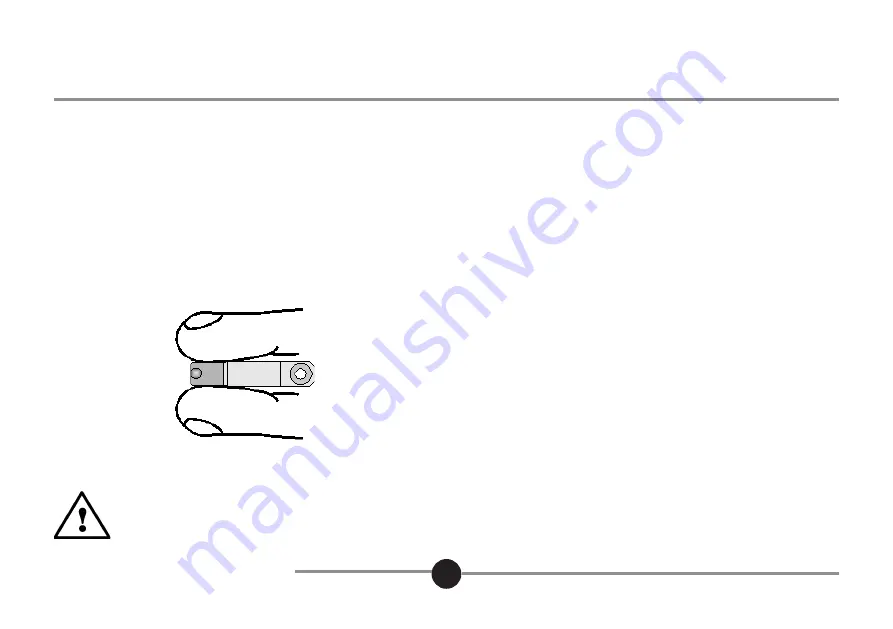
1) Firmly hold the Mini Probe frame as shown, so that it is
not stressed during the tip adjustment
2) Using the spanner supplied, turn the tip until the
required tip extension is achieved..
5.5: Tip Replacement
To remove tip
1) Firmly hold the Mini Probe frame, so that it is not
stressed during the tip removal.
2) Using the spanner supplied, unscrew the tip from
the Mini Probe.
To install tip
1) Firmly hold the Mini Probe frame, so that it is not
stressed during the tip installation.
2) Using the spanner supplied, screw the
replacement tip into the Mini Probe until the required
tip extension is achieved. The tip is self-locking, so a
tightening torque is not applicable. Do not tighten the
tip against the stop.
CAUTION
In order to avoid damage to the probe, it is critical that the Mini Probe is held firmly whilst the tip is being
adjusted. Failure to do so will stress the assembly and may damage the structure beyond repair.


