background image

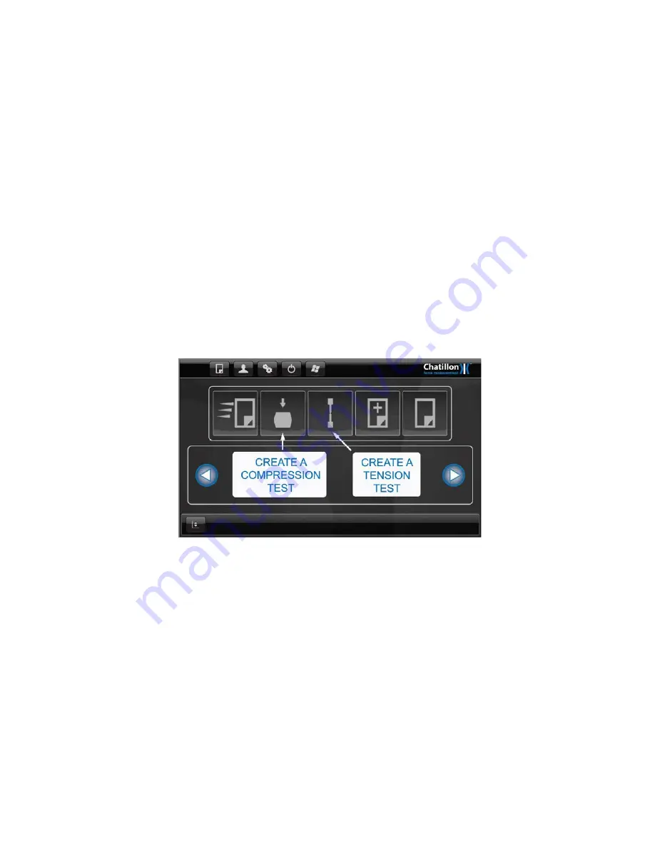
8.0 DEFINING A COMPRESSION OR TENSION TEST 

The "

Quick Test

" feature shown in section 7 does not store any test data in a test file so 

these tests cannot be analyzed at a later date. 


Therefore, 3 other options are provided to create test files that are used to store test results 
and graphical data and these files can be analyzed at a later date. 


8.1 CREATING A COMPRESSION TEST FILE 

This option is provided to create a Compression Test File. 


8.2 CREATING A TENSION TEST FILE 

This option is provided to create a Tension Test File. 


8.3 TEST FILE 

The test file is used to store the test parameters, test results and graphical data.  These files 
are used to test samples immediately after the file is created but can also be used to test 
further samples at a later date.  This allows the statistics of many samples to be viewed and 
analyzed. 


Please note that the creation of a Compression Test File and the Creation of a Tension Test 
File use the same procedures as shown in the following sections. 


Note that the machine can only store a maximum of 50 Tests. 


8.4 BASIC SETTINGS SCREEN 

Press the large "

COMPRESSION

" Icon on the "

HOME

" screen or the large "

TENSION

" Icon 

on the "

HOME

" screen (as required) to display the "

TEST SETTINGS

" screen. 


A test is created by moving through a sequence of configuration screens which is intuitive 
and easy to use. 


Each configuration screen has a "

HELP (?)

" button at the bottom of the screen and pressing 

this 

“?” 

button will display the relevant "

HELP

" screen. Each help screen only displays the 

information for the appropriate configuration screen for ease of use. 


50  CS User Manual


Содержание Chatillon CS1100

Страница 1: ...ustin Ft Worth NicolScales com 800 225 8181 Contact Us Nicol Scales Measurement is an ISO Accredited Calibration Company that has provided calibration repair and sales of all types of weighing and mea...

Страница 2: ...Part No 01 3953 MAY 2015 CS225 CS1100 Force Tester User Manual...

Страница 3: ...o responsibility for damage in transit and the purchaser should present any claims for such damage to the carrier TRADEMARKS AMETEK is a registered trademark of AMETEK Inc CHATILLON is a trademark of...

Страница 4: ...ries force tester with the lower cover removed Use an industrial qualityPower Surge Suppressor with your CS System Always make sure that the supply power matches the setting on the Power Input Module...

Страница 5: ...the operator other people machine and properties by providing guards shields screen adequate lighting adequate ventilation etc Furthermore when the machine is installed wired and ready for its intend...

Страница 6: ...s EN 61326 1 2006 Electrical equipment for measurement control and laboratory use EMC requirements General requirements BS EN 61326 2 3 2006 Electrical equipment for measurement control and laboratory...

Страница 7: ...2 8 CONNECTING THE LOAD CELL EXTERNAL CABLE 16 2 9 ON OFF SWITCH 16 2 10 EMERGENCY STOP SWITCH 17 2 11 LOAD CELLS 17 3 0 INITIAL CONFIGURATION 18 3 1 GENERAL 18 3 2 INITIAL LOG IN 18 3 3 LANGUAGES 20...

Страница 8: ...T SLOT TABLE 39 5 3 LOWER ANCHOR PIN 40 5 4 LIMIT STOPS 41 6 0 DEFINING A TEST 43 6 1 NOTES 43 7 0 SINGLE STAGE TEST WITHOUT SAVING DATA 44 7 1 BASIC SETTINGS SCREEN 44 7 2 TEST LIMITS SCREEN 46 7 3...

Страница 9: ...TAGE 70 9 12 ADDING A STAGE 70 9 13 TEST RESULTS SCREEN 71 9 14 ARCHIVE AND EXPORT SETTINGS SCREEN 75 9 15 DISPLAYING THE TEST GRAPH SCREEN 76 10 0 USING THE FORCE TESTER 77 10 1 PERFORMING A TEST 77...

Страница 10: ...BENCH 111 15 0 ERROR CONDITIONS 112 16 0 CLEANING AND MAINTENANCE 113 16 1 CLEANING EXTERNAL FINISH AND TRIM 113 16 2 MAINTENANCE 113 17 0 COMMUNICATIONS 114 17 1 CONFIGURING THE COMMUNICATIONS 114 17...

Страница 11: ...e is fitted with a PS2 mouse connector and 2 USB connectors on the right hand side One USB connector is used to connect the control console to the force tester frame and the other 2 connectors are onl...

Страница 12: ...een designed for indoor use It may occasionally be subjected to temperatures between 10 C and 35 C 14 F and 95 F without degradation of its safety 4 Before switching on the machine make sure that it i...

Страница 13: ...te training in basic operation before being allowed to use the machine Additional copies of this manual are available from AMETEK Inc 8 Operators must ensure that the Emergency Stop Button is never ob...

Страница 14: ...otherwise the results may be affected particularly for very low loads The Force Tester is required to be secured to the bench see section 14 CAUTION At no time should the CS Force Tester be lifted by...

Страница 15: ...elector from the 115V position to the 230V position as appropriate You MUST also check that the fuse rating is suitable for the supply voltage that you are using and the correct fuse values are listed...

Страница 16: ...d also ensure that the handscrew mechanism is towards the top of the control console Carefully lift the control console and position the free end of the spring clamp over the ball joint adaptor on the...

Страница 17: ...ad cell external cable is connected to the 15 way connector on the rear of the machine 2 9 ON OFF SWITCH The power input cable should be inserted into the mains input connector at the rear of the mach...

Страница 18: ...s provided Pressing the switch stops the CS Force Tester immediately It can be released by turning a quarter a turn clockwise The machine will then go to the initialize start up sequence if the ON OFF...

Страница 19: ...red to fully configure the system Connect the PC keyboard into the unused USB connector or the PS2 connector on the right hand side of the control console depending upon the keyboard connector Alterna...

Страница 20: ...tomatically start the dedicated force tester program and bypass the Windows log on screen Using a stylus double click on myuser to select all the text Enter administrator as the user name do not enter...

Страница 21: ...Icon Logout of the MyUser account and login to administrator no password required account Once in the administrator account select Start Run Explorer My Computer New Volume C Documents and Settings My...

Страница 22: ...on the next screen Note that the CURRENCY tab has no relevancy to the force tester Select OK to close the windows Then select Apply button Select the center tab Languages and the following screen will...

Страница 23: ...application will launch automatically To set up the Chinese language follow this procedure Logout of the CSx application by selecting the Windows Icon Logout of the MyUser account and login to adminis...

Страница 24: ...section select Chinese PRC Under Location section select China Then select Apply button Select the center tab Languages and the following screen will appear Select Details button and the following scr...

Страница 25: ...n press the Apply button Note There is not an available Simplified Chinese Keyboard available so the Chinese language will use an English keyboard Press OK to exit this screen and this main screen wil...

Страница 26: ...llowing message will appear Select the Yes button and the CS console will reboot Once the console is back to the MyUser account main Windows screen select Start Run Explorer My Computer New Volume C D...

Страница 27: ...AND TIME Using a stylus double click on the DATE AND TIME Icon in the Control Panel to display the settings screen Click on the TIME ZONE tab then select the required time zone using the drop down box...

Страница 28: ...iver may need to be installed by copying the files to a USB memory stick NOTE To select a new printer as the default it must be done in the MyUser account not administrator account To get to the MyUse...

Страница 29: ...ansfer this file to the folder If the Chatillon logo needs to be removed from PDF reports you can delete file in path C Documents and Settings MyUser Assets product_logo png If a second logo is requir...

Страница 30: ...PROGRAM FILES folder then double click on the EGALAXTOUCH folder to display a list of files Double click on XAUTO4PTSCAL then wait until a blank screen is displayed with a red circle and 4 arrows in t...

Страница 31: ...y the CONFIGURATION screen Press the ABOUT button on the left hand side of the screen if not already selected to display system information in the central area of the screen This central area shows th...

Страница 32: ...fication are required then one or more passwords must be created within the dedicated program To create a password press the USER SETTINGS button at the bottom of the screen to display the USER PASSWO...

Страница 33: ...a later date press on the unwanted user name then press the DELETE button Press on the CLOSE button to return to the CONFIGURATION screen The Force Tester can now only be used after a user has logged...

Страница 34: ...ways stop if the tensile or compressive force exceeds the load cell capacity This is to protect the load cell and frame from excessive forces This value may need to be reduced for special applications...

Страница 35: ...isplayed load value so the Force Tester must be re zeroed whenever grips are changed or removed before trying to re position the crosshead The maximum pinch load that can be set is 200N or 40lbf Howev...

Страница 36: ...ormation message when the load cell calibration is due The information message will be displayed after the time interval entered as the Load cell Calibration Interval To change the Load cell Calibrati...

Страница 37: ...cons along the top if the operator is defined as a User i e this operator has restricted access rights Home Screen for a Supervisor Home Screen for a User Note that a User can select tests and perform...

Страница 38: ...speed The Small Up arrow moves the crosshead upwards at the defined Slow Jog Speed and the Small Down arrow moves the crosshead downwards at the defined Slow Jog Speed In each case the crosshead only...

Страница 39: ...he Main screen as shown Press the POWER icon and the CS control console will shut down after a brief time period and indicate it is okay to power OFF the CS Series test machine Use the power switch in...

Страница 40: ...t can be adjusted up or down the Column Extrusion by loosening the thumbscrew Ensure there is plenty of length in the cable connected to the crosshead so that the crosshead can travel without pulling...

Страница 41: ...t should be adjusted so that it is accurately aligned with the pin on the attached load cell Carefully drive the crosshead downwards using the jog keys until the load cell eye end is just above the lo...

Страница 42: ...sen the lower limit stop screw and move the stop to the bottom of its travel in the slot Drive the moving crosshead to the lowest position that it may go to safely without damaging any fitted grips or...

Страница 43: ...essage will be displayed on the control console When the error display has been cleared the machine will only allow the operator to drive the crosshead away from the limit stop i e upwards if the lowe...

Страница 44: ...Previously Defined Test Perform Tests and Save Data 6 1 NOTES Option 1 does not store any test data although the data can be exported and or printed Options 2 3 and 4 create test files that are used...

Страница 45: ...printed if required 7 1 BASIC SETTINGS SCREEN Press the large QUICK TEST Icon on the HOME screen to display the TEST SETTINGS screen A test is created by moving through a sequence of configuration sc...

Страница 46: ...eload is required press on the PRELOAD FORCE entry area to display a numerical keypad enter the required value then press on the ENTER button If any numeric field needs to be edited after an initial v...

Страница 47: ...e tester is Zeroed before a BATCH of tests is started and NOT zeroed between each test Select the required Auto Return at End action using the control on the right hand side of the screen The force te...

Страница 48: ...numerical keypad enter the required value then press on the ENTER button To change the unit which will be initially set to the Default Force unit press the button to the right of the Distance entry ar...

Страница 49: ...ent or noise etc and the required threshold load starting load is entered in the Activate box 7 3 EXPORT SETTINGS SCREEN After the Limits have been set press on the NEXT button at the bottom of the sc...

Страница 50: ...Please refer to section 10 for details regarding test samples CS User Manual 49...

Страница 51: ...created but can also be used to test further samples at a later date This allows the statistics of many samples to be viewed and analyzed Please note that the creation of a Compression Test File and t...

Страница 52: ...he alphanumeric keypad then enter the required name for the test file Please note that if a Test Name is NOT entered then the system will automatically name the test files New Test followed by a seque...

Страница 53: ...code into the required field press on the edit box field above the keyboard to enable the field then scan the barcode If a preload force has been defined press on the PRELOAD SPEED entry area to displ...

Страница 54: ...pad enter the required value then press on the ENTER button To change the unit which will be initially set to the Default Force unit press the button to the right of the Test Speed entry area to cycle...

Страница 55: ...ption as shown above then define the Break operation using the controls on the right hand side of the screen See later e Stop at a Distance Value or when the Sample Breaks To stop the test at a distan...

Страница 56: ...ea to display an alphanumeric keypad Enter the required Label then press on the ENTER button Press on the Question entry area to display an alphanumeric keypad Enter the required Question then press o...

Страница 57: ...on the drop down button underneath it will display a second drop down list This list provides test results that are based upon general test information and contains NONE TIME DURATION OVERALL PASS FA...

Страница 58: ...d test result The Pass Fail values can be either Min Max or Variance Select the required option then enter the required values and units The test will be identified as a Pass if ALL Pass Fail paramete...

Страница 59: ...tamp select Export without timestamp option This option will allow the user to append data to the same file when exporting data in the same test multiple times The statistics data includes the maximum...

Страница 60: ...the archive the test data will go to the default location C Documents and Settings MyUser folder 8 9 DISPLAYING THE TEST GRAPH SCREEN After the Export Settings have been set press on the FINISH butto...

Страница 61: ...nation etc A Multi Action test can consist of Tensile Stages Compressive Stages Creep Hold Load Stages Relaxation Hold Extension Stages Zero Stages and Question Stages A Multi Action Test also provide...

Страница 62: ...Test followed by a sequential test number in brackets e g New Test 1 New Test 2 New Test 3 etc For information the test files are stored in the control console in a folder called C Documents and Setti...

Страница 63: ...ield then scan the barcode If a preload force has been defined press on the PRELOAD SPEED entry area to display a numerical keypad enter the required value then press on the ENTER button To change the...

Страница 64: ...tic or metal sample This is because the sample will generally have increased in length during the test so a compressive force will be applied to the load cell and grips as the crosshead returns at max...

Страница 65: ...ce at the specified distance target If a load limit is selected and the Ramping check box is checked the machine will not slow down at the end of the test and the load and distance that will be report...

Страница 66: ...ight hand side of the screen See later f Defining a Sample Break Decide what is considered to be sample break There are 2 methods provided to detect a sample break together with an optional threshold...

Страница 67: ...es 2 TENSION Stages that have stage limits of 10 in and 0 in respectively Note that the Return Stage is still a TENSION Stage because the crosshead does not move below the initial starting position Wh...

Страница 68: ...sition takes 18 seconds for each cycle The time at the end of cycle 1 is 18 seconds end of cycle 2 is 36 seconds end of cycle 3 is 54 seconds and end of cycle 4 is 72 seconds If a test duration of 60...

Страница 69: ...al mode to move the crosshead as necessary to maintain the specified load for the required time period Typical tests are foam tests carton tests paint can strength seal strength go no go The test eith...

Страница 70: ...be zeroed during a test by selecting a Zero Stage Press on the ZEROING button in the center of the screen to display the ZEROING screen Select ZERO LOAD VALUE and or ZERO DISTANCE VALUE as required No...

Страница 71: ...9 11 EDITING OR DELETING A STAGE A previously defined stage can be edited or deleted as required Select the required stage by pressing on it in the STAGE LIST shown on the right hand side of the scre...

Страница 72: ...ed in the STAGE LIST so the next stage will be added at the bottom of the STAGE LIST 9 13 TEST RESULTS SCREEN After all stages have been set press on the NEXT button at the bottom of the screen to dis...

Страница 73: ...FAIL RESULT RECORD NUMBER DATE and TIME If the TENSION STAGE or COMPRESSION STAGE option is selected using the top left drop down button then pressing on the drop down button underneath it will displa...

Страница 74: ...ed the controls to the right hand side of the result selectors are now enabled and these can be used to provide Pass Fail criteria for the selected test result The Pass Fail values can be either Min M...

Страница 75: ...t distance and an end distance The Custom Load Average Result will calculate the load average between the two configured distance points The Custom Load Average result is useful for peel type tests To...

Страница 76: ...headers option To export data without a timestamp select Export without timestamp option This option will allow the user to append data to the same file when exporting data in the same test multiple t...

Страница 77: ...archive is not available at the time of the archive the test data will go to the default location C Documents and Settings MyUser folder 9 15 DISPLAYING THE TEST GRAPH SCREEN After the Archive and Ex...

Страница 78: ...lease refer to section 11 The TEST GRAPH screen displays the test name at the top of the screen a Blank main area a load and distance display test result area and Start Test button as shown below The...

Страница 79: ...ill be displayed requesting this information Enter the relevant information then press on the OK button To enter a barcode into this dialog press on the dialog to enable it then scan the barcode When...

Страница 80: ...Bar does not reset to zero when the ZERO button is pressed on the Jog Control Panel For the CLC 250G load cell there may be a 10 shift on the load bar graph when nothing is attached to the load cell...

Страница 81: ...reen The CSx application will remember the screen that was showing when the test was started then return to this screen at the end of the test The picture above shows the default graph axes of Load Ti...

Страница 82: ...Unit of N and the previously defined default Distance Axis Unit of mm The graph load axis and load results will cycle through the available Load Axis units by repeatedly pressing the CHANGE FORCE UNI...

Страница 83: ...of the graph The left hand vertical area of the screen now displays two buttons marked 1 and 2 to show that 2 tests have been performed Both numbers are shown in green because the measured values are...

Страница 84: ...Break is detected then this is automatically marked on the graph as shown below A Marker can also be placed on the graph for any result by pressing on the required Result button to the left of the gra...

Страница 85: ...s to create a 2 cycle test A note can be added to any test by pressing on the white block in the Notes area and entering the required note or comment The next screen shows an example note 10 3 PRINTIN...

Страница 86: ...ow the graph to be recreated in Excel etc The data columns are Time Load Machine Extension and Extension if a Preload was not used OR Time Load Machine Extension and Extension from Preload if a Preloa...

Страница 87: ...e of test results or the calculated test statistics by using the VIEW buttons on the right hand side of the screen A table of test results is displayed by pressing on the DATA TABLE button The data ta...

Страница 88: ...same as the Excel STDDEVP method The standard deviation is a measure of how widely values are dispersed from the average value the mean The test results for a bad test e g test number 5 where the sam...

Страница 89: ...on at the top left of the screen to redisplay the HOME screen 10 5 PRINTING AND EXPORTING DATA TABLE AND STATISTICS When the data table or test statistics are displayed the test report can be printed...

Страница 90: ...results to the location identified in the export set up screen and then will clear the all the runs from the test The EXPORT RESULTS button creates a CSV comma delimited file that contains the Raw Gra...

Страница 91: ...4 07 42 18 11 12 11 12 12 36 12 20 40 14 28 34 03 40 15 10 6 TEST NOTES 1 If a percentage drop break detector is used to end the test the Force at Break value is not a True break value but is the spec...

Страница 92: ...r has restricted access rights Home Screen for a Supervisor Home Screen for a User A previously saved test file can be loaded by pressing on the large LOAD A SAVED TEST FILE Icon on the main screen or...

Страница 93: ...ance features as shown in section 10 7 The screens shown above list the test files in the Default order of Test Name i e the tests are listed in alphabetical order Note that if a Test Image was specif...

Страница 94: ...test file with the greatest number of tests is listed first then the other files are listed in descending order of number of tests If any test files have been assigned as Favorites see next section t...

Страница 95: ...rked as Favorites This simplifies the test selection because only specified test files are displayed on the main screen even if many more test files are stored in the internal memory To select a file...

Страница 96: ...top left of the screen to redisplay the HOME screen Note that the HOME screen now displays the Favorite files in the lower area These files will open and display the TEST GRAPH screen ready for testi...

Страница 97: ...select it then press on the COPY button The TEST SETTINGS screen is displayed with a Default Test Name of Copy of followed by the original test name e g Copy of Rubber Seal Type A Change the Test Name...

Страница 98: ...section 3 8 Alternatively the test file can be exported to a USB stick if this is connected into one of the unused USB sockets on the control console Display the TEST SELECTION screen press on the te...

Страница 99: ...sured and compensated by performing a special Test with either a VERY STIFF tension sample fitted into tensile grips or no sample fitted between compression plates Note that the Distance Compensation...

Страница 100: ...mpensation names 7 Select one of the Empty names e g Empty 0 Note that any previously defined Distance Compensation name may also be selected and replaced if no longer required 8 Press on the EDIT but...

Страница 101: ...s and a message will be displayed during the test action Note that this may take a couple of minutes depending upon the test speed 14 When the test has finished press on the CLOSE button to return to...

Страница 102: ...eated using a series of steps as shown below Note that this example sequence shows how to create a Height Mode test to measure the free length of a compression spring then measure the height of the sp...

Страница 103: ...TAGE screen 6 Note that the Icon at the left hand side of the SELECT NEXT STAGE screen shows Height Mode Red dot at the bottom of the vertical line 7 Press on the COMPRESSION button in the center of t...

Страница 104: ...he Test Speed to the required value 150mm min in the example screen above then select the Load option and set the Load to the value required for L2 Uncheck Ramping box 12 Press on the OK button to clo...

Страница 105: ...1 to display the list of Results then select Height at Preload HPL 17 Press on the top drop down control for result 2 to display the list of Stages then select 1 Compression Stage 18 Press on the bot...

Страница 106: ...Mode selected 2 Display the GRAPH screen ready for testing 3 Display the jog panel as shown in section 10 4 Use the jog panel to move the crosshead to a suitable position to allow the sample to be pla...

Страница 107: ...ple onto the bottom compression plate then press on the OK button 13 The test will be performed and test progress displayed in the Graph area 14 Note that the Live display on the left hand side of the...

Страница 108: ...16 Place the next sample onto the bottom compression plate then press on the green START button to perform the next test CS User Manual 107...

Страница 109: ...er or against solid specimens at high speed Load cells thus damaged cannot be repaired Ensure that the lower crosshead limit is set correctly See section 5 3 LIMIT STOPS 4 In compression tests if spec...

Страница 110: ...X 0 0001 lbf N Resolution 2 5 N X 0 0005 N CLC 0002 2 lbf X 0 0002 lbf 10 N X 0 001 N CLC 04 5 4 5 lbf X 0 0005 lbf 20 N X 0 002 N CLC 0010 10 lbf X 0 001 lbf 50 N X 0 005 N CLC 0020 20 lbf X 0 002 lb...

Страница 111: ...until the hinged shield is closed While not mandatory for many applications and countries CHATILLON strongly recommends that users consider fitting this optional item If a shield fitted with electron...

Страница 112: ...is secured to the bench using the 2 tapped holes in the base of the machine The template below shows the location of 2 holes that are required in the top of the workbench for the two M6 bolts The CS S...

Страница 113: ...started until the splinter shield is closed Cell Overload The load applied to the system is in excess of 110 of the loadcell rating Use the jog keys to remove the load Safety Overload The load applie...

Страница 114: ...oisture must ever be allowed to get into the testing frame Wipe the frame dry before connecting to the mains supply and restarting 16 2 MAINTENANCE In normal use and conditions your force testing fram...

Страница 115: ...er to the CS Console using the optional cable accessory part number SPK CS 0051 This cable is fitted between the RS232 connection 9 Pin D Type on the left hand side of the CS Control Console and the U...

Страница 116: ...perterminal and this must be set to use the same communication parameters as the Force Tester 17 2 USING THE COMMUNICATIONS Start the computer RS232 communications program then press on the START TERM...

Страница 117: ...E THE FORCE TESTER The Force Tester can be configured to move the crosshead until a Load or Distance measurement is reached The commands to achieve this are listed below Send Z to zero the LOAD value...

Страница 118: ...nd distance results with units continuously until the D command is requested Type character D then ENTER This stops the continuous sending of load and distance values in response to the n command G Se...

Страница 119: ...oad L and Distance D result displayed at the CS Console are both returned to zero S Request Load Values Continuously This ASCII command is used to request that load values be continuously transmitted...

Страница 120: ...command e is used to set the crosshead speed Use the prefix e with a numeric value to set the crosshead speed Type character e with a value then ENTER to specify the crosshead speed Example To set the...

Страница 121: ...tion status at the computer s Stop Crosshead Movement The ASCII command s is used to stop the crosshead movement It is used in conjunction with the command u move crosshead upward or d move crosshead...

Страница 122: ...entered Type character x then ENTER The instantaneous distance value is displayed at the computer y Stop Sending Continuous Distance Values The ASCII command t is used to request that distance values...

Страница 123: ...at Maximum Force 1 4mm 0 055in Maximum Weight of Machine 52kg 115lb Available Data Memory on CF Card 10 GB 18 2 TECHNICAL SPECIFICATION CS1100 Maximum Force Tension and Compression 5000N 1124lbf Cross...

Страница 124: ...0 B Width excluding control console 460 18 1 C Depth 557 21 9 D Base Height 108 4 3 E Throat Depth 180 7 1 CS1100 mm in A Height 1301 51 2 B Width excluding control console 460 18 1 C Depth 557 21 9 D...

Страница 125: ...20 0 RoHS TABLES Restricted Substance Status Table 1 Restricted Substance Status Table 2 124 CS User Manual...

Страница 126: ...CS User Manual 125...

Страница 127: ...21 0 SPARE PARTS KITS SPK CS225 Sheet A 126 CS User Manual...

Страница 128: ...SPK CS225 Sheet B CS User Manual 127...

Страница 129: ...H ASSEMBLY 13 SPK LS 0016 SAFE LINE SWITCH ASSEMBLY 14 SPK LS 0017 LOAD CELL LOOM ASSEMBLY 15 SPK CS 0018 CONTROL CONSOLE USB CABLE 16 SPK LS 0019 ENCODER LOOM ASSEMBLY 17 SPK LS 0020 SAFE LINE LOOM A...

Страница 130: ...500mm TRAVEL 37 SPK LS 0040 TOP COVER 38 SPK CS 0041 LOWER EYE END ASSEMBLY 39 SPK LS 0042 POWER SUPPLY UNIT 40 SPK LS 0043 RUBBER FEET SET OF 4 41 SPK LS 0046 A POWER CORD ASSEMBLY 115 VAC US MAINS...

Страница 131: ...SPK CS1100 Sheet A 130 CS User Manual...

Страница 132: ...SPK CS1100 Sheet B CS User Manual 131...

Страница 133: ...SEMBLY 13 SPK LS 0016 SAFE LINE SWITCH ASSEMBLY 14 SPK LS 0017 LOAD CELL LOOM ASSEMBLY 15 SPK CS 0018 CONTROL CONSOLE USB CABLE 16 SPK LS 0019 ENCODER LOOM ASSEMBLY 17 SPK LS 0020 SAFE LINE LOOM ASSEM...

Страница 134: ...039B LINEAR RAIL ASSEMBLY 800mm TRAVEL 37 SPK LS 0040 TOP COVER 38 SPK CS 0041 LOWER EYE END ASSEMBLY 39 SPK LS 0042 POWER SUPPLY UNIT 40 SPK LS 0043 RUBBER FEET SET OF 4 41 SPK LS 0046 A POWER CORD A...

Страница 135: ...ral lloyd instruments ametek fr Germany AMETEK Europe GmbH Rudolf Diesel Strasse 16 D 40670 Meerbusch Germany Tel 49 0 2159 9136 0 Fax 49 0 2159 9136 39 info ametek de Singapore AMETEK Singapore Pte L...

Отзывы: