background image

Page 5

User Guide

Landmark Technic

Signal Processor

3  Installation and Removal

3.1  Fitting the unit onto a DIN rail

The LM Technic processor is designed to be mounted onto a standard DIN rail.  

To install the unit:
1)  Ensure that a suitable DIN rail (DIN EN 50 022) is available and installed  

correctly (refer to Appendix).

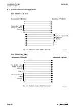
2)  Refer to Fig. 3.  Rest the uppermost groove on the rear of the processor  

on the top lip of the DIN rail.

3)  Push the bottom of the unit so that the sliding spring catch clips onto the 

DIN rail.

3.2  Removing the unit from a DIN rail

1)  Refer to Fig. 4.  Insert a screwdriver into the sliding spring catch via the 

slot  on the underside of the unit.

2)  Lever the sliding spring catch downwards so that it disengages from the 

DIN rail.

3)  Lift the processor off the DIN rail.

3.3  Electrical connections

The LM Technic processor is designed to be used in conjunction with the Land 

DPU Power Supply Unit.
To prevent damage to the equipment, ensure that the DPU (power supply) 

and signal processor are fully interconnected, before switching on the mains 

power supply.
The LMT to DPU wiring interconnections are given in Fig. 5 (overleaf).
The LMT wiring schedule is given in Table 1.
The DPU wiring schedule is given in Table 2.

Connections to the configuration port are given in Table 3 - Appendix B.

Содержание System 4 Landmark Technic Processor

Страница 1: ...Landmark Technic Processor User Guide Issue 7 22 November 2016 Publication N 198 213 Language English Copyright 2002 2016 Land Instruments International...

Страница 2: ...e user documentation supplied before installing and operating the equipment The safety of any system incorporating this equipment is the responsibility of the assembler Protective Clothing Face and Ey...

Страница 3: ...ent damage during transit You must include a written report of the problem together with your own name and contact information address telephone number email address etc Design and Manufacturing Stand...

Страница 4: ...Landmark Technic Signal Processor User Guide...

Страница 5: ...on and Removal 5 3 1 Fitting the unit onto a DIN rail 5 3 2 Removing the unit from a DIN rail 5 3 3 Electrical connections 5 3 4 Cable connector assembly 10 4 Using the Configurator 11 4 1 Installatio...

Страница 6: ...Landmark Technic Signal Processor User Guide Fig 1 Landmark Technic Signal Processor...

Страница 7: ...for a single LAND System 4 thermometer Features include DIN rail mounting case Averager Peak Picker and Track and Hold for signal processing Remote input for Track and Hold Control Peak Picker Reset...

Страница 8: ...Signal Processor User Guide alarm averager peak picker track hold emissivity command input config serial i o alarm output current output no time function output scaling RS 232 IRT Fig 2 LM Technic Fu...

Страница 9: ...63 in 15 steps Peak Picker decay range 0 25 s to 512 s in 12 steps threshold 1 steps on delay 0 to 10s in 0 1s steps off delay 0 to 10s in 0 1s steps reset mode Hold reset Track Hold Controlled by ext...

Страница 10: ...ssor User Guide DIN rail Sliding spring catch Clip onto DIN rail Fig 3 Installing the LM Technic onto a DIN rail LMT010065 Screwdriver Use a screwdriver to unclip the spring latch Fig 4 Removing the L...

Страница 11: ...l 1 Refer to Fig 4 Insert a screwdriver into the sliding spring catch via the slot on the underside of the unit 2 Lever the sliding spring catch downwards so that it disengages from the DIN rail 3 Lif...

Страница 12: ...4 5 6 7 8 Processor Supply Live Neutral Twisted Pair Twisted Pair Screened Twisted Pair Processor Supply 6 core screened cable to IRT Pigtails maximum length 30mm NOTE The LM Technic processor is desi...

Страница 13: ...ck Thermometer power supply 7 Green Emissivity return 8 Not applicable Do not use 9 Alarm relay 1 10 Alarm relay 2 11 Command 12 Command 13 Signal out 14 Signal out 15 Signal out Screen 16 Processor p...

Страница 14: ...0V Switch open 1 5V Switch closed Fig 6 CMD Command input control via a remote switch S4970387 1 2 CMD Open Circuit Peak Picker Track Hold Short Circuit Peak Pick Reset Track Hold Note Potential free...

Страница 15: ...en circuit i e Track The command signal is active when the voltage is 1 5V or short circuit i e Hold The command input can be controlled via a remote switch as shown in Fig 6 or via potential free con...

Страница 16: ...e cable tie clamp bar 3 Wire up the connector remembering the correct orientation of the plug in accordance with the relevant cable schedule see Section 3 3 4 Ensure that the cable outer insulation is...

Страница 17: ...to run alone with configuration stored into it s non volatile memory 4 1 Installation Run the file on the CD and follow the Installation Instructions 4 2 Getting Started After the power supply has bee...

Страница 18: ...If a single colour thermometer has been select ed enter the desired emissivity for the material being measured If a 2 colour ratio thermometer has been selected enter the non greyness 5 Output The cur...

Страница 19: ...ply When the required configuration parameters have been en tered press the Apply button to send the configuration data to the LM Technic 4 A summary of the data sent will appear in the live data conf...

Страница 20: ...time function S4970092 Time Temp 0V V Command Command signal Closure of potential free contacts TTL level 0 to 5V or 0 to 24V Track Track Hold Hold s c Hold 5V Track 24V Track 0V Hold Fig 11 Graphical...

Страница 21: ...ature output signal falls to under range until the tem perature input next rises above the threshold level The Peak Picker can be Reset at any time by using the CMD input See 3 3 2 Decay rate A user a...

Страница 22: ...ications in order of precedence LED A Colour Indication Amber Test mode Flashing Amber Volatile configuration Flashing Green Configurator connected Green OK LED B Colour Indication Red Sensor fail Fla...

Страница 23: ...ndmark Technic Processor is designed to be virtually maintenance free but calibration checks are highly recommended at periods of not more than one year For details on Landmark Technic calibration ple...

Страница 24: ...27 0 2 35 0 3 1 0 04 r r 25 18 Plain RS Stock N Length 176 652 176 668 1 0m 2 0m Punched RS Stock N Length 424 131 606 838 0 5m 1 0m 27 0 2 35 0 3 0 0 2 1 5 0 05 r r 27 0 2 25 18 Plain RS Stock N Leng...

Страница 25: ...th either terminals or computers which allows communications with a single processor only RS485 contact Land Instruments International Serial Communications specification Mode selection RS232C Baud ra...

Страница 26: ...Landmark Technic x x x CR LF Parameter value being requested ASCII x A Value or requested parameter ASCII Fig 14 RS232C mode READ protocol LMT010075 Fig 15 RS232C mode WRITE protocol LMT010076 Compute...

Страница 27: ...enter Press terminal enter key Reply 1000 Temperature in degrees To set the emissivity to 0 500 Type at the terminal SAEMS 500 enter Breakdown S Set mode A Always A EMS Command to work on the emissiv...

Страница 28: ...unction 0 3 1 0 0 None 1 Averager 2 Peak picker 3 Track Hold PPM Peak picker mode 0 1 1 0 0 Reset 1 Hold PPT Peak picker threshold irt_ tmin irt_ tmax 1 irt_tmin value in degrees e g 1051C Limits and...

Страница 29: ...0 irt_ tmax 5 irt_tmax value in degrees Additional limit on value ensures t_max t_min 100 OMN Signal output Tmin mA irt_ tmin irt_ tmin 100 5 irt_tmin value in degrees LBL Channel label Full char acte...

Страница 30: ...Active Active Active Active Active Active Not active OK OK OK OK OK OK MEM Memory Function 0000 9999 0001 0000 Read response 0000 RAM Flash Read response 0001 RAM Flash Flag is set when configuration...

Страница 31: ...plies will disrupt internal timing and affect time function processing Inter command timing This is the time between the end of the last character of a command received by the LM Technic and the end o...

Страница 32: ...Page 26 Landmark Technic Signal Processor User Guide...

Страница 33: ...truments based on System 4 UNO thermometers accessories and mountings and special instruments based on UNO Application dedicated processors based on LANDMARK Graphic ABTS S and ABTS U FTS VDT S and VD...

Страница 34: ...ide the Ambient Temperature Humidity and Vibration rating of the product environmental contamination solvent vapours deposition of airborne contamination cooling liquids of non neutral pH etc overheat...

Отзывы: