


Part No. 37-7775005
09/2020 11-HD17D1-1C-EN 5
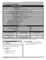
American Standard Silver 302 and 303 Touchscreen Thermostat
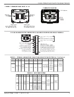
Mounting
Hole
Mounting
Hole
Place Level
across Mounting Tabs
(for appearance only)
Place Level
across Mounting Tabs
(for appearance only)
+
S
HM
-
W/E
6
DHM
Y2
O/B
L
Y
W2
THERMOSTAT REARVIEW
2 "AA" Batteries
Power
Stealing
Switches
Stack
Power
Stealing
Switch
FIGURE 2. THERMOSTAT BASE PLATE
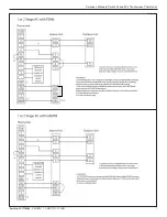
302 / 303
+
HM
S
-
W1
6
DHM
W2
Supplies voltage to remote temperature
sensor
Remote Temperature Sensor Terminals
Supplies voltage to remote temperature
sensor
Whole House Humidification (HM)
— 303 ONLY
Humidification Terminal, energizes
on call for heat if humidity setpoint is
above room humidity. Can also be
used to provide humidification
independnent of a call to heat and/or
in cooling mode if Automatic
Humidification is selected in
Configuration Menu item #42
Enhanced Cooling
Dehumidification (DHM) —303 ONLY
De-energizes on call for Dehumidification to
lower the variable speed fan speed by 20%.
The DHM terminal is only used on systems
with a compatible dehumidification feature
that has the required terminal connection on
the control module or BK terminal on indoor
models with variable speed blower motors.
Y2
O/B
L
Y
+
HM
S
-
W1
6
DHM
W2
COOLING DEHUMIDIFICATION, HUMIDIFICATION, AND REMOTE TEMPERATURE SENSOR TERMINALS
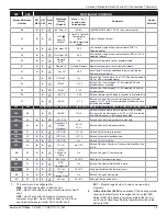
FIGURE 3. – TERMINAL DESIGNATIONS SINGLE STAGE OR MULTI-STAGE SYSTEM:
Heat / Cool Systems
Single Stage 1
(SS1)
Multi Stage 2
(MS2)
System
RC
RH
C
Y
Y2
W/E
W2
G
O/B
6
L
Call for heat
Heat mode-1st
stage
Heat mode-2nd
stage
No output
24 volt
power for
cooling
24 volt
power for
heating
Cool mode-2nd
stage
24 volt
common
(optional
for system
operation,
required
for remote
sensor)
Call for cool
No Output
Cool mode-1st
stage
Blower/Circulator fan
energized on a call
for cool or Fan On
(also energized in
heating if configured
for Electric Heat)
Installer
Configuration
Menu selects
“O” or “B” for
changeover
function. Set
to “O” terminal
energized in Cool
& Off mode. Set
to “B” terminal
energized in
Heat & mergency
mode
Power closed
connection for
SPDT 3-wire
zone valve
Fault or System
Malfunction
Indicator for
Heat Pumps
with “L” terminal
connection.
FIGURE 4. – HEAT PUMP SYSTEMS
Heat
Pump 1
(HP1)
Heat
Pump 2
(HP2)
System
RC
RH
C
Y
Y2
*W/E
*W2
G
O/B
6
L
Heat mode-2nd
stage, Emergency
Mode-1st stage
*Note: Dual Fuel
option de-
energizes Heat
mode stage 1
(compressor)
when auxiliary
heat is energized
Heat mode-3rd
stage, Emergency
Mode-1st stage
*Note: Dual Fuel
option de-
energizes Heat
mode stages 1
and 2 (both
compressors)
when auxiliary
heat is energized
Heat mode-4th
stage, Emergency
Mode-2nd stage
*Note: Dual Fuel
option de-
energizes Heat
mode stages 1
and 2 (both
compressors)
when auxiliary
heat is energized
Heat mode-3rd
stage, Emergency
Mode-2nd stage
*Note: Dual Fuel
option de-
energizes Heat
mode stage 1
(compressor)
when auxiliary
heat is energized
24 volt
power for
cooling
24 volt
power for
heating
Heat mode-2nd
stage,
Cool mode-2nd
stage,
(Compressor)
No Output
24 volt
common
(optional
for system
operation,
required
for remote
sensor)
Heat mode-1st
stage,
Cool mode-1st
stage,
(Compressor)
Blower/Circulator fan
energized on a call
for cool or Fan On
(also energized in
heating if configured
for Electric Heat)
Installer
Configuration
Menu selects
“O” or “B” for
changeover
function. Set
to “O” terminal
energized in Cool
& Off mode. Set
to “B” terminal
energized in
Heat & mergency
mode
Power closed
connection for
SPDT 3-wire
zone valve
Fault or System
Malfunction
Indicator for
Heat Pumps
with “L” terminal
connection.