background image

INSTALLATIONS


12


MB950 User’s Manual


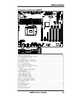
Connectors on MB950 

 
Connector Locations on MB950 ........................................................ 13


CN1: PS/2 Keyboard and PS/2 Mouse Connectors ............................ 14


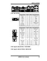
CN3: COM1 and COM3 Serial Ports ................................................. 14


CN2: VGA and DVI .......................................................................... 15


CN5: Gigabit LAN (82583V) + USB2/USB3 .................................... 15


CN6: Gigabit LAN (82578DM) + USB0/USB1 ................................. 15


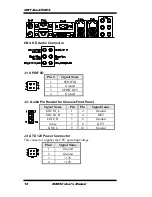
CN4: HD Audio Connector ............................................................... 16


J3: ATX 12V Power Connector ......................................................... 16


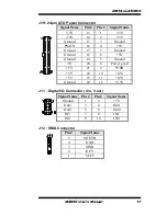
J19: 24-pin ATX Power Connector .................................................... 17


J16, J17, J18, J22, J23, J24: SATA II Connectors .............................. 17


J13: Front Panel Function Connector ................................................. 18


J1: SPDIF I/O .................................................................................... 16


J2 : Audio Pin Header for Chassis Front Panel ................................... 16


J11 : Digital I/O Connector (4 in, 4 out) ............................................ 17


J12 : IRDA Connector ....................................................................... 17


F_USB1: USB4/USB5 Connector ..................................................... 18


F_USB2: USB6/USB7 Connector ..................................................... 19


F_USB3: USB8/USB9 Connector ..................................................... 19


F_USB4: USB10/USB11 Connector ................................................. 19


F_USB5: USB12/USB13 Connector ................................................. 19


CPU_FAN1:  CPU Fan Power Connector .......................................... 20


SYS_FAN1:  system Fan1 Power Connector ..................................... 20


J20, J21: COM4, COM2 RS232 Serial Ports 


J26: Parallel Port Connector .............................................................. 19


CN7: CF Socket ................................................................................ 20


J4: ISA Slot (shared with PCI4) ......................................................... 20


PCIE1: PCI-E X16 (PEG) ................................................................. 20


PCIE2: PCI-E X1 Slot ....................................................................... 20


PCIE3: PCI-E X8 Slot (X4 Link) ...................................................... 20


PCI1-PCI4: PCI 32-bit Slot ............................................................... 20


Содержание MB950

Страница 1: ...MB950 Intel Core i3 i5 i7 ATX Motherboard USER S MANUAL Version 1 0A ...

Страница 2: ...of International Business Machines Corporation Intel are registered trademarks of Intel Corporation Microsoft Windows is a registered trademark of Microsoft Corporation Winbond is a registered trademark of Winbond Electronics Corporation All other product names or trademarks are properties of their respective owners ...

Страница 3: ... MB950 Specifications 3 Board Dimensions 4 Installations 5 Installing the CPU 6 Installing the Memory 7 Setting the Jumpers 8 Connectors on MB950 12 BIOS Setup 21 Drivers Installation 43 Appendix 55 A I O Port Address Map 55 B Interrupt Request Lines IRQ 56 C Watchdog Timer Configuration 57 ...

Страница 4: ...i7 processor is installed the memory module should be installed in DIMM1 socket otherwise the system will not boot 2 When an external graphics card is installed on the motherboard regardless of they type of processor on board the onboard VGA and DVI ports connectors will not function Use the graphics output connector on the graphics card 3 The onboard PCI E x8 slot supports PCI E x4 link only Plea...

Страница 5: ...treams in combination of the onboard VGA CRT and DVI D video interfaces Up to 16GB of maximum memory can be configured in four DDR3 socket at 1066 1333MHz In addition to the impressive computing performance the board is equipped with high end connectivity comprised of dual Gigabit LAN controllers six SATA II ports one IDE fourteen USB 2 0 ports four COM ports and high definition audio Should great...

Страница 6: ...2 MB950 User s Manual Checklist Your MB950 package should include the items listed below The MB950 ATX motherboard This User s Manual 1 CD containing chipset drivers and flash memory utility Cable kit IDE Serial ATA ...

Страница 7: ...ller ALC888 Codec w 7 1 channels LPC I O Winbond W83627UHG COM1 RS232 422 485 COM2 RS232 COM3 RS232 COM4 RS232 with pin 9 with power for 4 ports 500 mA for each port Hardware monitor 2 thermal inputs 4 voltage monitor inputs VID0 4 2 Fan Headers Digital IO 4 in 4 out iAMT Q57 built in iAMT 6 0 MB950AF only KB Mouse Supports PS 2 Keyboard Mouse connector Expansion Slots 1x PCI e x16 slot 1x PCI e x...

Страница 8: ...INTRODUCTION 4 MB950 User s Manual Board Dimensions ...

Страница 9: ...ations This section provides information on how to use the jumpers and connectors on the MB950 in order to set up a workable system The topics covered are Installing the CPU 6 Installing the Memory 7 Setting the Jumpers 8 Connectors on MB950 12 ...

Страница 10: ... 90 degree Then position the CPU above the socket such that the CPU corner aligns with the gold triangle matching the socket corner with a small triangle Carefully insert the CPU into the socket and push down the lever to secure the CPU Then install the heat sink and fan NOTE Ensure that the CPU heat sink and the CPU top surface are in total contact to avoid CPU overheating problem that would caus...

Страница 11: ...ules locate the memory slot on the board and perform the following steps 1 Hold the DDR3 module so that the key of the DDR3 module aligned with that on the memory slot 2 Gently push the DDR3 module in an upright position until the clips of the slot close to hold the DDR3 module in place when the DDR3 module touches the bottom of the slot 3 To remove the DDR3 module press the clips with both hands ...

Страница 12: ...nfiguration for your needs The following lists the connectors on MB950 and their respective functions Jumper Locations on MB950 9 JP1 JP2 JP3 RS232 RS422 RS485 COM1 Selection 10 JP4 COM1 RS232 RI 5V 12V Power Setting 10 JP5 COM3 RS232 RI 5V 12V Power Setting 10 JP9 COM4 RS232 RI 5V 12V Power Setting 10 JP11 COM2 RS232 RI 5V 12V Power Setting 11 JP7 Compact Flash Socket Master Slave Setting 11 JP8 ...

Страница 13: ... JP2 JP3 RS232 RS422 RS485 COM1 Selection 10 JP4 COM1 RS232 RI 5V 12V Power Setting 10 JP5 COM3 RS232 RI 5V 12V Power Setting 10 JP9 COM4 RS232 RI 5V 12V Power Setting 10 JP11 COM2 RS232 RI 5V 12V Power Setting 11 JP7 Compact Flash Socket Master Slave Setting 11 JP8 Clear CMOS Contents 11 ...

Страница 14: ... 1 3 2 4 JP3 1 3 2 4 JP4 COM1 RS232 RI 5V 12V Power Setting JP4 Setting Function Pin 1 2 Short Closed 12V Pin 3 4 Short Closed RI Pin 5 6 Short Closed 5V JP5 COM3 RS232 RI 5V 12V Power Setting JP5 Setting Function Pin 1 2 Short Closed 12V Pin 3 4 Short Closed RI Pin 5 6 Short Closed 5V JP9 COM4 RS232 RI 5V 12V Power Setting JP9 Setting Function Pin 1 2 Short Closed 12V Pin 3 4 Short Closed RI Pin ...

Страница 15: ... JP11 Setting Function Pin 1 2 Short Closed 12V Pin 3 4 Short Closed RI Pin 5 6 Short Closed 5V JP7 Compact Flash Socket Master Slave Setting JP7 Compact Flash Master Slave JP8 Clear CMOS Contents JP8 Setting Function Pin 1 2 Short Closed Normal Pin 2 3 Short Closed Clear CMOS ...

Страница 16: ...t Panel Function Connector 18 J1 SPDIF I O 16 J2 Audio Pin Header for Chassis Front Panel 16 J11 Digital I O Connector 4 in 4 out 17 J12 IRDA Connector 17 F_USB1 USB4 USB5 Connector 18 F_USB2 USB6 USB7 Connector 19 F_USB3 USB8 USB9 Connector 19 F_USB4 USB10 USB11 Connector 19 F_USB5 USB12 USB13 Connector 19 CPU_FAN1 CPU Fan Power Connector 20 SYS_FAN1 system Fan1 Power Connector 20 J20 J21 COM4 CO...

Страница 17: ...3 Front Panel Function Connector 18 J1 SPDIF I O 16 J2 Audio Pin Header for Chassis Front Panel 16 J11 Digital I O Connector 4 in 4 out 17 J12 IRDA Connector 17 F_USB1 USB4 USB5 Connector 18 F_USB2 USB6 USB7 Connector 19 F_USB3 USB8 USB9 Connector 19 F_USB4 USB10 USB11 Connector 19 F_USB5 USB12 USB13 Connector 19 CPU_FAN1 CPU Fan Power Connector 20 SYS_FAN1 system Fan1 Power Connector 20 J20 J21 C...

Страница 18: ...rd Mouse Signal Name Keyboard data 1 1 Mouse data N C 2 2 N C GND 3 3 GND 5V 4 4 5V Keyboard clock 5 5 Mouse clock N C 6 6 N C CN3 COM1 and COM3 Serial Ports Pin Signal Name RS 232 R2 422 RS 485 1 DCD TX DATA 2 RX TX DATA 3 TX RX NC 4 DTR RX NC 5 Ground Ground Ground 6 DSR NC NC 7 RTS NC NC 8 CTS NC NC 9 RI NC NC 10 NC NC NC ...

Страница 19: ... 10 GND N C 11 12 DDCDATA HSYNC 13 14 VSYNC DDCCLK 15 Signal Name Pin Pin Signal Name DATA2 1 2 DATA2 GND 3 4 N C N C 5 6 DDCCLK DDCDATA 7 8 N C DATA1 9 10 DATA1 GND 11 12 N C N C 13 14 VCC GND 15 16 Hot Plug Detect DATA0 17 18 DATA0 GND 19 20 N C N C 21 22 GND CLK 23 24 CLK CN5 Gigabit LAN 82583V USB2 USB3 CN6 Gigabit LAN 82578DM USB0 USB1 ...

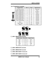
Страница 20: ...d 3 SPDIF OUT 4 Ground J2 Audio Pin Header for Chassis Front Panel Signal Name Pin Pin Signal Name MIC IN_L 1 2 Ground MIC IN_R 3 4 DET LINE_R 5 6 Ground Sense 7 8 KEY LINE_L 9 10 Ground J3 ATX 12V Power Connector This connector supplies the CPU operating voltage Pin Signal Name 1 Ground 2 Ground 3 12V 4 12V ...

Страница 21: ... PS ON 16 4 5V Ground 17 5 Ground Ground 18 6 5V Ground 19 7 Ground 5V 20 8 Power good 5V 21 9 5VSB 5V 22 10 12V 5V 23 11 12V Ground 24 12 3 3V J11 Digital I O Connector 4 in 4 out Signal Name Pin Pin Signal Name Ground 1 2 5V Out3 3 4 Out1 Out2 5 6 Out0 IN3 7 8 IN1 IN2 9 10 IN0 J12 IRDA Connector Pin Signal Name 5 SOUTB 4 GND 3 SINB 2 KEY 1 VCC5 ...

Страница 22: ...ED GND SPK GND 7 8 NC NC 9 10 NC AMT LED 11 12 AMT LED PWR_SW 13 14 PWR_SW NC 15 16 NC RST 17 18 GND HDD LED 19 20 HDD LED J16 J17 J18 J22 J23 J24 SATA II Connectors Pin Signal Name 1 Ground 2 TX 3 TX 4 Ground 5 RX 6 RX 7 Ground J20 J21 COM4 COM2 RS232 Serial Ports Signal Name Pin Pin Signal Name DCD 1 6 DSR SIN 2 7 RTS SOUT 3 8 CTS DTR 4 9 RI GND 5 X KEY ...

Страница 23: ...18 Ground PD4 parallel data 4 6 19 Ground PD5 parallel data 5 7 20 Ground PD6 parallel data 6 8 21 Ground PD7 parallel data 7 9 22 Ground ACK acknowledge 10 23 Ground Busy 11 24 Ground Paper empty 12 25 Ground Select 13 N A N A F_USB1 USB4 USB5 Connector Signal Name Pin Pin Signal Name VCC 1 2 VCC D0 3 4 D1 D0 5 6 D1 GND 7 8 GND KEY 9 10 NC F_USB2 USB6 USB7 Connector F_USB3 USB8 USB9 Connector F_U...

Страница 24: ...al Name 1 Ground 2 12V 3 Rotation detection 4 Control SYS_FAN1 system Fan1 Power Connector Pin Signal Name 1 Ground 2 12V 3 Rotation detection CN7 CF Socket J4 ISA Slot shared with PCI4 PCIE1 PCI E X16 PEG PCIE2 PCI E X1 Slot PCIE3 PCI E X8 Slot X4 Link PCI1 PCI4 PCI 32 bit Slot ...

Страница 25: ...AMI BIOS that comes with the board The topics covered in this chapter are as follows BIOS Introduction 22 BIOS Setup 22 Main BIOS Setup 23 Advanced Settings 24 PCIPnP Settings 35 Boot Settings 37 Security Settings 38 Advanced Chipset Settings 39 Exit Setup 42 Load Optimal Defaults 42 Load Failsafe Defaults 42 ...

Страница 26: ...diately activated Pressing the Del key immediately allows you to enter the Setup utility If you are a little bit late pressing the Del key POST Power On Self Test will continue with its test routines thus preventing you from invoking the Setup If you still wish to enter Setup restart the system by pressing the Reset button or simultaneously pressing the Ctrl Alt and Delete keys You can also restar...

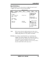
Страница 27: ...sor Intel R Core TM i5 CPU 660 3 33GHz Speed 3333MHz Count 1 System Memory Size 8056MB System Time 02 29 50 System Date Fri 01 02 2009 Note If the system cannot boot after making and saving system changes with Setup the AMI BIOS supports an override to the CMOS settings that resets your system to its default Warning It is strongly recommended that you avoid making any changes to the chipset defaul...

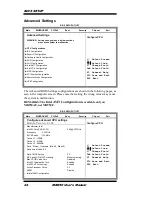
Страница 28: ...following pages as seen in the computer screen Please note that setting the wrong values may cause the system to malfunction REMARKS The Intel AMT Configuration is available only on MB950AF not MB950F BIOS SETUP UTILITY Main Advanced PCIPnP Boot Security Chipset Exit Configure advanced CPU settings Module Version 01 08 Configure CPU Select Screen Select Item Change Field Tab Select Field F1 Genera...

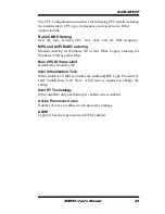
Страница 29: ...ering for Windows XP or later OSes Legacy ordering for Windows 2000 or earlier OSes Max CPU ID Value Limit Disabled for Windows XP Intel Virtualization Tech When enabled a VMM can utilize the additional HW Caps Provided by Intel Vitualization Tech Note A full reset is required to change the setting Intel HT Technology When disabled only one thread per enabled core is enabled Active Processor Cores...

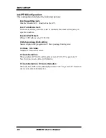
Страница 30: ...c condition Intel C STATE tech CState CPU idle is set to C2 C3 C4 C State package limit setting Selected option will program into C State package limit register C3 State C6 State Nehalem C state action select C1 Auto Demotion When enabled CPU will conditionally demote C3 C6 C7 requests to C1 based on uncore auto demote information C1 Auto Demotion C3 Auto Demotion When enabled CPU will conditional...

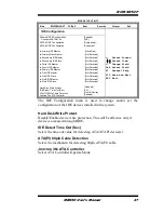
Страница 31: ...IDE Master Not Detected Fifth IDE Master Not Detected Fifth IDE Slave Sixth IDE Master Sixth IDE Slave Hark Disk Write Protect IDE Detect Time Out Sec ATA PI 80Pin Cable Detection Jmicron 36x ATA Controller Not Detected Not Detected Not Detected Disabled 35 Host Device Enabled The IDE Configuration menu is used to change and or set the configuration of the IDE devices installed in the system Hard ...

Страница 32: ...t Parallel Port These fields allow you to select the onboard serial ports and their addresses The default values for these ports are Serial Port 1 3F8 Serial Port 2 2F8 Serial Port 3 3E0 IRQ10 Serial Port 4 Disabled Parallel Port 378 IRQ7 Parallel Port Mode This field allows you to determine parallel port mode function SPP Standard Printer Port EPP Enhanced Parallel Port ECP Extended Capabilities ...

Страница 33: ...SYSTEM Speed 0 RPM CPUFAN0 Speed 5400 RPM Vcore V 1 160 V 5V 12V 3 3V 5 273V 12 196 V 3 392 V 1 5V 1 520 V VBAT CPU smart fan 3 21 V Disabled ACPI Shut down Temperature Disabled The Hardware Health Configuration menu is used to show the operating temperature fan speeds and system voltages CPU smart fan The options are Disabled 55ºC 60ºC 65ºC 70ºC 75ºC 80ºC and 85ºC ACPI Shutdown Temperature The op...

Страница 34: ...t General ACPI Configuration BIOS SETUP UTILITY Main Advanced PCIPnP Boot Security Chipset Exit General ACPI Configuration General ACPI Configuration settings Select Screen Select Item Change Field Tab Select Field F1 General Help F10 Save and Exit ESC Exit Suspend mode Auto Repost Video on S3 Resume No Suspend Mode The options of this field are S1 S3 and Auto Repost Video on S3 Resumet Determines...

Страница 35: ...ng BIOS control otherwise operates in IDE mode AHCI Port While entering setup BIOS auto detects the presence of IDE devices This displays the status of auto detection of IDE devices BIOS SETUP UTILITY Main Advanced PCIPnP Boot Security Chipset Exit Intel AMT Configuration Options Disabled Enabled Select Screen Select Item Change Field Tab Select Field F1 General Help F10 Save and Exit ESC Exit Int...

Страница 36: ...ion capabilities one physical computer system can function as multiple virtual systems BIOS SETUP UTILITY Main Advanced PCIPnP Boot Security Chipset Exit MPS Configuration Select MPS Revision Select Screen Select Item Change Field Tab Select Field F1 General Help F10 Save and Exit ESC Exit MPS Revision VT d 1 4 MPS Version Control for OS This option is specifies the MPS Multiprocessor Specificatio...

Страница 37: ...e 1115200 8 n 1 Flow Control None Redirection After BIOS POST Always Terminal Type ANSI VT UTF8 Combo Key Support Enabled Sredir Memory Display Delay No Delay When enabled the Remote Acces type and parameters are shown Serial port number Select Serial Port for console redirection Serial port mode Select Serial Port settings Flow Control Select Flow Control for console redirection Redirection After...

Страница 38: ...en Select Item Change Field Tab Select Field F1 General Help F10 Save and Exit ESC Exit Module Version 2 24 5 14 4 USB Devices Enabled 2 Hubs Legacy USB Support Enabled USB 2 0 Controller Mode HiSpeed BIOS EHCI Hand Off Disabled Legacy USB1 1 HC Support Enabled USB Beep Message Disabled Legacy USB Support Enables support for legacy USB AUTO option disables legacy support if no USB devices are conn...

Страница 39: ...SA IDE Card Auto IRQ3 Available IRQ4 Available IRQ5 Available IRQ7 Available IRQ9 Available IRQ10 IRQ11 IRQ14 IRQ15 DMA Channel 0 DMA Channel 1 DMA Channel 3 DMA Channel 5 DMA Channel 6 DMA Channel 7 Reserved Memory Size Available Available Available Available Available Available Available Available Available Available Disabled Clear NVRAM This item is used for clearing NVRAM during system boot Pl...

Страница 40: ...led in the system so the card will function correctly PCI IDE BusMaster This uses PCI busmastering for BIOS reading writing to IDE devices OffBoard PCI ISA IDE Card Some PCI IDE cards may require this to be set to the PCI slot number that is holiding the card AUTO Works for most PCI IDE cards IRQ Use the IRQ address to specify what IRQs can be assigned to a particular peripheral device Reserved Me...

Страница 41: ...o skip certain tests while booting This will decrease the time needed to boot the system Quite Boot Disabled Displays normal POST messages Enabled Displays OEM Logo instead of POST messages Bootup Num Lock Select Power on state for Numlock PS 2 Mouse Support Select support for PS 2 Mouse Wait for F1 If Error Wait for F1 key to be pressed if error occurs Hit DEL Message Display Displays Press DEL t...

Страница 42: ...o type it again After setting a password the screen automatically returns to the main screen To disable a password just press the Enter key when you are prompted to enter the password A message will confirm the password to be disabled Once the password is disabled the system will boot and you can enter Setup freely BIOS SETUP UTILITY Main Advanced PCIPnP Boot Security Chipset Exit Security Setting...

Страница 43: ...ge Configuration ME Subsystem Configuration BIOS SETUP UTILITY Main Advanced PCIPnP Boot Security Chipset Exit North Bridge Chipset Configuration Disabled 15MB 16MB Select Screen Select Item Change Field Tab Select Field F1 General Help F10 Save and Exit ESC Exit Memory Remap Feature Enabled DRAM Frequency Auto Configure DRAM Timing by SPD Auto Memory Hole Disabled Initiate Graphic Adapter PEG PCI...

Страница 44: ...system memory used by the internal graphics device PEG Port The options are Auto and Disabled PEG Force GEN1 Some non graphics PCI E devices may not follow PCI E specifications and may incorrectly report their GEN capability or link width Video Function Configuration The configuration allows setting to DVMT FIXED memory Main Advanced PCIPnP Boot Security Chipset Exit Video Function Configuration D...

Страница 45: ...LAN PXE Boot Disabled Second LAN 82583 PXE Boot Disabled Wake On PCIE LAN Enabled Wake On PCI PME Enabled Wake On Ring Enabled Wake On RTC Alarm Disabled HDA Controller Enabled SMBUS Controller Enabled SLP_S4 Min Assertion Width 4 to 5 seconds HDA Controller This option is used to enable the Southbridge high definition audio controller BIOS SETUP UTILITY Main Advanced PCIPnP Boot Security Chipset ...

Страница 46: ...ot to accept the modifications and save all changes into the CMOS memory before exit Discard Changes and Exit This option allows you to exit the Setup utility without saving the changes you have made in this session Discard Changes This option allows you to discard all the changes that you have made in this session Load Optimal Defaults This option allows you to load the default values to your sys...

Страница 47: ...t the vendor where you made the purchase The contents of this section include the following Intel Chipset Software Installation Utility 44 Intel Graphics Driver Installation 46 Realtek HD Codec Audio Driver Installation 48 LAN Drivers Installation 49 Intel Management Engine Interface 51 IMPORTANT NOTE After installing your Windows operating system Windows 2000 XP Vista you must install first the I...

Страница 48: ...nder Windows 2000 XP Vista Before installed Intel Chipset Software Installation Utility Please update your system to Windows 2000 SP4 or Windows XP SP1A 1 Insert the DVD that comes with the board Click Intel and then Intel R Chipset Software Installation Utility 3 When the Welcome screen appears click Next to continue 4 Click Yes to accept the software license agreement and proceed with the instal...

Страница 49: ...S INSTALLATION MB950 User s Manual 45 6 When the Setup Progress screen appears click Next to continue 7 The Setup process is now complete Click Finish then restart the computer and for changes to take effect ...

Страница 50: ...Intel Graphics Driver Installation 1 Insert the DVD that comes with the board Click Intel Intel Q57 Chipset Family Graphics Driver 2 When the InstallShield Wizard screen appears click Next 3 When the Welcome screen appears click Next to continue ...

Страница 51: ...nse agreement and proceed with the installation process 5 On Readme File Information screen click Next to continue 6 On Setup Progress screen click Next to continue the installation 7 The Setup process is now complete Click Finish to restart the computer and for changes to take effect ...

Страница 52: ...the DVD that comes with the board Click Intel and then Realtek High Definition Audio Driver 2 Click Realtek High Definition Codec Audio Driver 3 When the Welcome screen appears click Next to continue 4 The Setup process is now complete Restart the computer when prompted for changes to take effect ...

Страница 53: ...d Click Intel and then Intel R PRO LAN Network Drivers 2 Click Intel R PRO LAN Network Drivers 3 On the next screen click Install Drivers to start the drivers installation 4 When the Welcome screen appears click Next to continue 5 In the License Agreement screen click I accept the terms in license agreement and Next to accept the software license agreement and proceed with the installation process...

Страница 54: ...pears click Drivers as shown below and Next to continue 7 When the Ready to Install the Program screen appears click Install to continue 8 The Setup process is now complete InstallShield Wizard Completed Click Finish to restart the computer and for changes to take effect ...

Страница 55: ...ivers can be installed on MB950AF not MB950F 1 Insert the drivers disc that comes with the motherboard Click Intel and then Intel R AMT 6 0 Drivers When the welcome screen of the Intel Management Engine Components appears click Next to continue On the next screen click Next to agree to the license agreement ...

Страница 56: ...DRIVER INSTALLATION 52 MB950 User s Manual 2 On the next screen the Readme File Information shows the system requirements and installation information click Next ...

Страница 57: ...IVERS INSTALLATION MB950 User s Manual 53 3 When the Setup Progress screen appears click Next to continue Then click Finish when the setup progress has been successfully installed to restart the computer ...

Страница 58: ...DRIVER INSTALLATION 54 MB950 User s Manual This page is intentionally left blank ...

Страница 59: ...oller 1 020h 03Fh Interrupt Controller 1 040h 05Fh Timer 060h 06Fh Keyboard Controller 070h 07Fh Real Time Clock NMI 080h 09Fh DMA Page Register 0A0h 0BFh Interrupt Controller 2 0C0h 0DFh DMA Controller 2 0F0h Clear Math Coprocessor Busy Signal 0F1h Reset Math Coprocessor 1F0h 1F7h IDE Interface 2E8h 2FFh Serial Port 4 COM4 2F8h 2FFh Serial Port 2 COM2 2B0 2DF Graphics adapter Controller 3C0 3CF E...

Страница 60: ...red The following table shows the IRQ used by the devices on board Level Function IRQ0 System Timer Output IRQ1 Keyboard IRQ2 Interrupt Cascade IRQ3 Serial Port 2 4 IRQ4 Serial Port 1 3 IRQ5 Reserved IRQ6 Reserved IRQ8 Real Time Clock IRQ9 Reserved IRQ10 Reserved IRQ11 Reserved IRQ12 PS 2 Mouse IRQ13 80287 IRQ14 Primary IDE IRQ15 Secondary IDE ...

Страница 61: ...EITHER EXPRESSED OR IMPLIED INCLUDING BUT NOT LIMITED TO THE IMPLIED WARRANTIES OF MERCHANTABILITY AND OR FITNESS FOR A PARTICULAR PURPOSE include dos h include conio h include stdio h include stdlib h include F81865 H int main int argc char argv void EnableWDT int void DisableWDT void int main int argc char argv unsigned char bBuf unsigned char bTime char endptr char SIO printf Fintek 81865 watch...

Страница 62: ...APPENDIX 58 MB950 User s Manual Set_F81865_Reg 0x2B bBuf Enable WDTO ...

Страница 63: ...bBuf disable WDTO output bBuf Get_F81865_Reg 0xF5 bBuf 0x20 bBuf 0x40 Set_F81865_Reg 0xF5 bBuf disable WDT THIS CODE AND INFORMATION IS PROVIDED AS IS WITHOUT WARRANTY OF ANY KIND EITHER EXPRESSED OR IMPLIED INCLUDING BUT NOT LIMITED TO THE IMPLIED WARRANTIES OF MERCHANTABILITY AND OR FITNESS FOR A PARTICULAR PURPOSE include F81865 H include dos h unsigned int F81865_BASE void Unlock_F81865 void v...

Страница 64: ...81865_Reg unsigned char REG unsigned char Result Unlock_F81865 outportb F81865_INDEX_PORT REG Result inportb F81865_DATA_PORT Lock_F81865 return Result THIS CODE AND INFORMATION IS PROVIDED AS IS WITHOUT WARRANTY OF ANY KIND EITHER EXPRESSED OR IMPLIED INCLUDING BUT NOT LIMITED TO THE IMPLIED WARRANTIES OF MERCHANTABILITY AND OR FITNESS FOR A PARTICULAR PURPOSE ifndef __F81865_H define __F81865_H ...

Страница 65: ...APPENDIX MB950 User s Manual 61 ...

Отзывы: