Chapter 1 Hardware Installation
25
Step 7 Attach Cables,
Continued
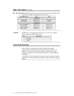
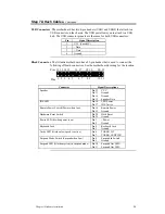
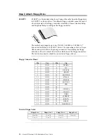
USB Connectors The motherboard has two 4-pin headers (USB1 and USB2) that attach to a
USB connector on the chassis. The USB port allows you to attach to a USB
hub. The USB connector pinouts are the same for both USB connectors:
Pin
Signal Description
1
VCC (Fused 5V)
2
- Data
3
+ Data
4
Ground
Block Connector The Atlantis motherboard has a 22-pin header that is used to connect the
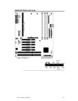
following offboard connectors. See the motherboard drawing for the location.
Pins 12 13 14 15
16 17
18 19
20 21
1 2 3 4
5
6 7
8 9
10 11
Pins
Connector
Signal Descriptions
Speaker
Pin 12
VCC
Pin 13
Ground
Pin 14
Ground
Pin 15
Speaker Data
IDE LED
Pin 16
LED Power
Pin 17
IDE Active
Remote Power Switch (Power when low).
Pin 18
Remote Power
Pin 19
Ground
Hardware Reset Switch
Pin 20
Hard Reset
Pin 21
Ground
Power LED (lit when power is on)
Pin 1
+Power
Pin 2
Ground
Keyboard Lock
Pin 4
Keyboard Lock
Pin 5
Ground
Turbo LED (lit when low speed is active)
Pin 6
TURBO_LIT
Pin 7
TURBO_LEDPWR
Suspend Mode Switch (Suspend when Low)
Pin 8
Suspend In Switch
Pin 9
Ground
Suspend LED (lit when system in suspend mode)
Pin 10
Suspend Out LED+
Pin 11
Suspend Out LED-
Содержание Atlantis Pentium II PCI ISA
Страница 1: ...Atlantis Pentium II PCI ISA Motherboard Guide MAN 773 11 20 97 ...
Страница 38: ......
Страница 75: ...Chapter 3 Programming the Flash ROM 71 ...

