


Apollo-II PCI Pentium ISA Motherboard User’s Guide
18
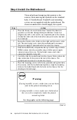
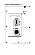
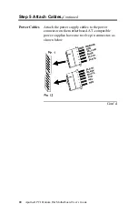
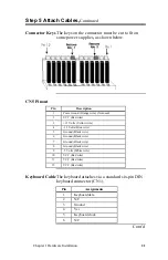
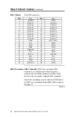
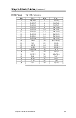
Step 5 Attach Cables
Connectors
The Apollo II motherboard includes many
connectors. Connection instructions, illustrations
of connectors, and pinouts are supplied in the
following pages. A list of all connectors described
in this section follows:
Connector
Turn to
JCP Clear password
page 19
CPU Fan J7
page 23
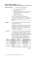
Power supply connector CN5
page 19
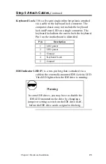
Keyboard connector CN1
page 21
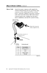
Mouse connector CN4
page 22
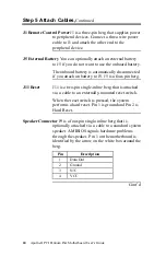
Remote Control Power J1
Page 24
External Battery J5
Page 24
Reset switch J11
page 24
Speaker J9
page 24
Keyboard lock connector J10
page 24
IDE LED connector JP1
page 24
Serial port connectors CN7 and CN6
page 26
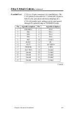
Parallel port connector CN8
page 27
Floppy connector CN9
page 28
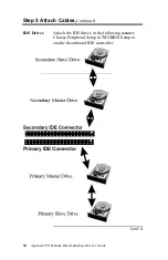
IDE drive connectors IDE1 and IDE2
pages 31 through 33
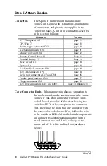
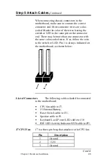
Cable Connector Ends
When connecting chassis connectors to
the motherboard, make sure to connect the correct
connector end. Most connector wires are color-
coded. Match the color of the wires leaving the
switch or LED to the same pin on the connector
end. There may be more than one connector with
the same color-coded wires. If so, follow the wire
to the switch or LED. All motherboard components
are outlined by a white rectangular box with a
broad arrow at one end. Pin 1 is always at the
arrow end of the white outlined box, as shown
below:
Cont’d