3
AMI
EXCELLENCE IN MAGNETICS AND CRYOGENICS
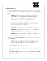
C. Ensure the front panel power switch is in the OFF (
2
) position. Verify that the
instrument is configured for the proper operating voltage by referring to the label
adjacent to the power entry module on the rear panel of the instrument. If the
operating voltage is correct, plug the line cord into the appropriate power receptacle.
WARNING: The Model 4Q05100PS operates on 50-60 Hz power and
may be configured for 100-120 or 200-240 VAC. The power requirement
for each instrument is marked on the rear panel of the instrument
adjacent to the power entry module. Be sure your instrument is
configured for your power source prior to plugging in the line cord. Do
not fail to connect the input ground terminal securely to an external
earth ground.
If the instrument operating voltage needs to be changed, the unit must be returned to
AMI.
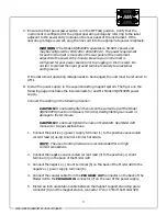
D. Install the power supply in the superconducting magnet system. The figure on the
following page illustrates the interconnects for an AMI Model 4Q05100PS power
supply.
Connect the cabling in the following manner:
CAUTION: Do not overtighten the nuts on the current lugs of the Model
4Q05100PS (maximum torque is 50 in-lbs).Overtightening can result in
damage to the terminals.
CAUTION: Do not overtighten the nuts on Model 420. See Model 420
manual for torque specifications.
1. Connect the positive (+) power supply terminal (1) to the positive vapor-cooled
current lead (2) using 1/4-20 or similar hardware.
NOTE: The use of locking hardware is recommended for all high
current connections.
2. Connect the negative vapor-cooled current lead (3) to the positive (+) shunt
terminal (4) on the back of the Model 420.
3. Connect the negative (
−
) shunt terminal (5) on the back of the Model 420 to the
negative (
−
) power supply terminal (6).
4. Connect the coaxial cable from the
352*5$0287
connector on the back of the
Model 420 to the
352*5$0,1
connector (7) on the rear of the power supply.
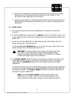
5. Install an instrumentation cable between the magnet support stand top plate
connector (8) and the magnet station connector J7A or J7B of the Model 420.


