American Dynamics AD100 Скачать руководство пользователя страница 8

8     Recorder Controller/Interface Installation Instructions

8000-1796-01, Rev. B

Testing Recorder Commands

Testing IR Commands via PC

Prior to final hookup of the AD1024 system with
recorder interface hardware, it is advisable to test the IR
command set with the system video recorders in a “test
bench” setting.
This will verify the proper operation of the recorder
interface modules while isolating the test from the
physical complexities of the actual site installation.

Connecting the IR Emitter Cables

1.


Connect the IR emitter cable mini-plugs into the
appropriate IR jacks on the AD100IR16 modules.
Note: the module’s 16 IR connectors are labeled
IR-1 through IR-16 (see Drawing 3, page 5).

2.


Attach the adhesive emitter to the appropriate
location on the video recorder under test. If
necessary, consult the recorder manufacturer’s
instructions to verify the proper location.

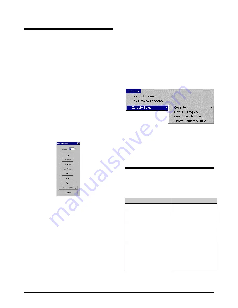
Testing the Recorder Command Set

1.


Select 

Functions/Test Recorder Commands

. The

Test Recorder

 dialog box appears.

2.


Using the up and down arrows to the right of the
spin box, set the recorder # to a value between 1
and 2048. Test the seven recorder command
functions by pressing the command buttons in
sequence.

3.


Repeat step 2 for each recorder in the system, or, if
the number of system recorders is large and the
time allotted for testing is limited, randomly select
a smaller sub-set of the total number of recorders
and test their command functions.

Testing Commands with AD1024

1.


After testing the recorder commands with the PC,
disconnect the serial cable from the PC COM port.
Disconnect the DB9F adaptor from the modular
cable. Connect the RJ-45 connector to the
Peripheral Interface Port (PIP) of the AD1024
CPU.

Settings for the PIP are as follows:

Baud rate

9600

Data Bits

8

Stop Bits

1

Parity

None

2.


Using the AD2088 keyboard, call up each of the
system video recorder and test each of the recorder
command functions (see Drawing 4, page 9).

Notes on Controller Setup Functions

When the 

Functions

 menu is selected, 

Controller Setup

provides two options in addition to the two already
discussed:


Comm Port

 enables the user to choose COMM 1, 2,

3, or 4 on the PC used for system setup.


Default IR Frequency

 – Typical video recorders are

set to an IR frequency of 38 KHz. If a recorder
manufacturer’s specifications indicate a different
frequency, the 

Default IR Frequency

 dialog box

enables the user to set a value ranging from 20 to
150 KHz.

Upgrade Kits and Peripherals

The following table lists the upgrade kits and
peripherals that are required for the applicable AD
matrix switcher/controller systems to accommodate
video recorder control operations:

Matrix Switcher/Controller System

Required Upgrade Kits & Peripherals

AD1024

 MegaPower II Matrix

Switcher/Controller System

None required

AD2050 

MegaPower II Matrix

Switcher/Controller System


AD1024CPUKIT Upgrade Kit for
existing AD1996CPU


AD2088 Full System Keyboard

AD2052 

MegaPower II WIP Matrix

Switcher/Controller System


AD1024CPU MegaPower CPU


AD1024S3 System Setup Software


AD2010DB Data Receiver/Buffer for
AD2010R and AD2020R Bays


AD2088 Full System Keyboard

AD1995 

MegaPower Matrix

Switcher/Controller System


AD1024CPU MegaPower CPU


Firmware for AD1609R and
AD1625R Bays


AD1024S3 System Setup Software


AD2088 Full System Keyboard


Other Components must be
specified by Applications
Engineering.

Содержание AD100

Страница 1: ...ill also support recorder control Particular systems developed before AD1024 can support recorder control with appropriate upgrade equipment see the table on page 8 for details The AD Recorder Controller interface is available for both 120 VAC and 230 VAC applications Equipment Provided see Drawing 1 Page 3 Part Qty Part No Recorder Controller 120 VAC 1 AD100XA Recorder Controller 230 VAC 1 AD100X...

Страница 2: ...When used in concert with the recorder controller and utility software the IR interface module can control any recorder having IR capability Up to 2048 IR video recorders can be controlled on the network Each IR interface module is supplied with a transformer to power the unit RIU Recorder Interface Utility In order to implement the programming of the IR Interface Modules each Recorder Controller ...

Страница 3: ...quipment AD100 Series System Drawings Drawing 1 System Equipment AD100XA Front View This connector not used AD100XA Rear View AD100IR16 Front View AD100IR16 Rear View Modular Cable with DB9F DB9M Adaptors AD100IRE Emitter Cable 120 VAC Transformer 230 VAC Transformer Opening for Addressing Switch ...

Страница 4: ...called riu exe resides in the RIU folder 4 A new folder called Recorder Library resides in the C drive 5 Four VCR files are installed in the Recorder Library folder The filenames refer to four standard VCRs denoted by brand name and model number Launching the Application On the Windows desktop click the following sequence 1 Start 2 Programs 3 American Dynamics 4 Recorder Installation Utility The i...

Страница 5: ...ler Interface Installation Instructions 5 Drawing 2 Daisy Chain Configuration Drawing 3 AD100 Interface w PC Video Recorders AD100 Series System Drawings Drawing 2 Daisy Chain Configuration Drawing 3 AD100 Interface w PC Video Recorders ...

Страница 6: ...order Types If the system utilizes recorder types other than those provided as RIU default models the user must map the non default model s and learn the IR command set appropriate to the model s To map additional recorder types and learn the appropriate IR command sets perform the following steps 1 Select Functions Learn IR Commands The Recorder Library dialog box again appears see illustration u...

Страница 7: ...he right most Recorder Types column in the row adjacent to the appropriate output number click and drag to assign the selected recorder type to multiple outputs 4 Click on the arrow in the center of the initial RIU window The selected recorder type will appear to the right of the appropriate output s Assigning Recorder Numbers to Outputs 1 To assign a recorder number click in the Recorder cell to ...

Страница 8: ...the DB9F adaptor from the modular cable Connect the RJ 45 connector to the Peripheral Interface Port PIP of the AD1024 CPU Settings for the PIP are as follows Baud rate 9600 Data Bits 8 Stop Bits 1 Parity None 2 Using the AD2088 keyboard call up each of the system video recorder and test each of the recorder command functions see Drawing 4 page 9 Notes on Controller Setup Functions When the Functi...

Страница 9: ...8000 1796 01 Rev B Recorder Controller Interface Installation Instructions 9 Drawing 4 AD100 Interface w AD1024 System Drawing 4 AD100 Interface w AD1024 System ...

Страница 10: ... in Height 1 38 in AD100IR16 1 Length 5 50 in Width 3 25 in Height 1 38 in Environmental Specifications Operating Temp 5 C to 40 C 40 F to 104 F Humidity 95 non condensing Storage Temp 40 C to 70 C 40 F to 155 F Approvals UL UL listed transformer with device CSA CSA certified transformer provided w device CE CE marked transformer provided with device Warranty Disclaimer Sensormatic Electronics Cor...

Страница 11: ...ntonio Cork Ireland Aguadilla P R 00690 Declares that the product s listed below Name Type AD100 Series Recorder Interface Modules Model Numbers AD100XA 1 AD100IR16 1 comply with the EMC Standards EN55022 Class B EN50082 1 and also comply with the following safety standard EN60950 Each module is provided with an external power supply Additional information These products herein comply with the req...

Страница 12: ...12 Recorder Controller Interface Installation Instructions 8000 1796 01 Rev B Sensormatic Video Systems Division 1 Blue Hill Plaza Pearl River New York 10965 914 624 7600 ...

Отзывы: