background image

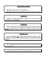
FOR YOUR SAFETY

DO NOT

 DRY MOP HEADS IN THE DRYER.

DO NOT 

USE DRYER IN THE PRESENCE OF DRY CLEANING FUMES.

WARNING

UNDER  NO  CIRCUMSTANCES  should  the  door  switch  or  the  heat

circuit devices ever be disabled.

WARNING

The dryer must never be operated with any of the back guards, outer tops,

or  service  panels  removed.    PERSONAL  INJURY  or  FIRE  COULD

RESULT.

IMPORTANT

PLEASE  OBSERVE ALL  SAFETY  PRECAUTIONS  displayed  on  the

equipment and/or specified in the installation/operator's manual included with

the dryer.

Dryer(s) 

must not

 be installed or stored in an area where it will be exposed to

water and/or weather.

The wiring diagram for the dryer is located in the front electrical control box area.

All manuals and user guides at all-guides.com

Содержание Gas/Steam Models ML-82

Страница 1: ...ent Installation and service must be performed by a qualifiedinstaller serviceagencyorthegas supplier AVERTISSEMENT Assurez vousdebien suivrelesinstructionsdonnéesdanscette noticepourréduireauminimumlerisque d incendieoud explosionpourouévitertout dommagematériel touteblessureoulamort Ne pas entreposer ni utiliser d essence ni d autresvapeursouliquidesinflammablesdans le voisinagede cet appareil o...

Страница 2: ...ke this manual as complete as possible and hope you will find it useful ADC reserves the right to make changes from time to time without notice or obligation in prices specifications colors and material and to change or discontinue models Important For your convenience log the following information DATE OFPURCHASE ____________________________ MODEL NO __________________________________________ DIS...

Страница 3: ...nal Safety and Health Administration STANDARDS CHILDREN SHOULD NOT BE ALLOWED TO PLAY ON OR NEAR THE DRYER S WARNING CHILDREN SHOULD BE SUPERVISED IF NEAR DRYER S IN OPERATION CAUTION LABEL ALL WIRES PRIOR TO DISCONNECTION WHEN SERVICING CONTROLS WIRING ERRORS CAN CAUSE IMPROPER AND DANGER OUS OPERATION DRYER S SHOULD NEVER BE LEFT UNATTENDED WHILE IN OPERATION CAUTION VERIFY PROPER OPERATION AFTE...

Страница 4: ... guards outer tops or service panels removed PERSONAL INJURY or FIRE COULD RESULT IMPORTANT PLEASE OBSERVE ALL SAFETY PRECAUTIONS displayed on the equipment and or specified in the installation operator s manual included with the dryer Dryer s must not be installed or stored in an area where it will be exposed to water and or weather The wiring diagram for the dryer is located in the front electri...

Страница 5: ...S 10 A LocationRequirements 10 B Unpacking SettingUp 11 C DryerEnclosureRequirements 12 D FreshAirSupply 13 E ExhaustRequirements 14 F ElectricalInformation 20 G GasInformation 23 H SteamInformation 27 I Preparation For Operation Start Up 31 J PreoperationalTests 32 K PreoperationalInstructions 34 L ShutDownInstructions 34 SECTION IV SERVICE PARTS INFORMATION 35 A Service 35 B Parts 35 All manuals...

Страница 6: ...ng 38 B Adjustments 39 C Lubrication 40 D LintDrawerRemoval 40 SECTION VII PROCEDURE FOR FUNCTIONAL CHECK OF REPLACEMENT COMPONENTS 41 SECTION VIII DATA LABEL LOCATION INFORMATION 45 A Data Label 45 SECTION IX BURNER AND LINT TUMBLER CHAMBER MANUAL RESET HI LIMIT INSTRUCTIONS 47 All manuals and user guides at all guides com a l l g u i d e s c o m ...

Страница 7: ...received and the number refused must be noted on the receipt 4 If you determine that the dryer was damaged after the trucker has left your location you should call the delivering carrier s freight terminal immediately and file a claim The freight company considers this concealed damage This type of freight claim is very difficult to get paid and becomes extremely difficult when more than a day or ...

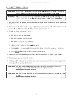
Страница 8: ...h any electrical switch c DO NOT use any phone in your building d Clear the room building or area of ALL occupants e Immediately call your gas supplier from a neighbor s phone Follow the gas supplier s instructions f If you cannot reach your gas supplier call the fire department 4 Installation and service must be performed by a qualified installer service agency or gas supplier 5 Dryer s must be e...

Страница 9: ...e ANSI NFPA NO 70 LATEST EDITION or in Canada the Canadian Electrical Codes Parts 1 2 CSA C22 1 1990 or LATEST EDITION NOTE Failure to do so willVOIDTHEWARRANTY 9 UNDER NO CIRCUMSTANCES should the dryer door switches lint drawer switch or heat safety circuit ever be disabled WARNING PERSONALINJURYorFIRE COULD RESULT 10 This dryer is not to be used in the presence of dry cleaning solvents or fumes ...

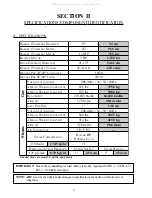
Страница 10: ...BLE 208 460v 3ø 50 60Hz APPROX WEIGHT UNCRATED 828 lbs 392 7 kg APPROX WEIGHT CRATED 914 lbs 415 5 kg AIRFLOW 2 500 cfm 98 8 cmm AIR CONNECTION 1 8 F P T STEAM COMSUMPTION BOILER HP NORMAL LOAD 375 lbs hr 170 5 kg hr 11 OPERATING STEAM PRESSURE STEAM SUPPLY STEAM RETURN 125 psi max 8 79 kg cm2 1 2 54 cm 1 2 54 cm Shaded areas are stated in metric equivalents Gas Steam SECTION II SPECIFICATIONS COM...

Страница 11: ...ifications ML 82 Gas and Steam ONLY NOTE ADC reserves the right to make changes in specifications at any time without notice or obligation All manuals and user guides at all guides com a l l g u i d e s c o m ...

Страница 12: ...cription 1 Controls 2 Control top access Door Assembly 3 Main DoorAssembly 4 Lint Compartment Area lint screen located behind door 5 Lint Drawer 6 Data Label and Installation Label located behind control service door All manuals and user guides at all guides com ...

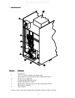
Страница 13: ...or Steam Models ONLY 3 Electric Service Relay Box 4 Tumbler Bearing MountAssembly 5 Idler Bearing MountAssembly 6 Basket Drive Motor Assembly for Reversing Models ONLY 7 Blower Motor Assembly 8 Dryer Exhaust Electric service connections for gas models and steam models are made in this box All manuals and user guides at all guides com ...

Страница 14: ...nd level floor capable of supporting its weight Carpeting must be removed from the floor area that the dryer is to rest on IMPORTANT The dryer mustbeinstalledonnoncombustiblefloorsonly 2 The dryer must not be installed or stored in an area where it will be exposed to water and or weather 3 The dryer is for use in noncombustible locations 4 Provisions for adequate air supply must be provided as not...

Страница 15: ...at must be installed on the outlet of the exhaust before any further venting is connected To do this follow the procedures listed below a Remove the exhaust transition piece from the basket tumbler and place it on the exhaust outlet b Using the screws provided secure the exhaust transition piece to the dryer NOTE It is recommended that this joint be taped as well as ALLotherductjointstopreventmois...

Страница 16: ... cm clearance is required NOTE Allowances must be made for opening the control door Dryers may be positioned side wall to side wall However a 1 16 1 5875 mm minimum allowance must be made for opening and closing of the control door and the lint door It is suggested that the dryer be positioned about 2 feet 0 61 meters away from the nearest obstruction for ease of installation maintenance and servi...

Страница 17: ...nition problems and sail switch fluttering problems may result as well as premature motor failure from overheating Air supply make up air must be given careful consideration to assure proper performance of each dryer An unrestricted source of air is necessary for each dryer An airflow of 1 700 cfm cubic feet per minute 48 14 cmm cubic meters per minute must be supplied to each gas and electric dry...

Страница 18: ... be laid out in such a way that the duct work travels as directly as possible to the outdoors with as few turns as possible Single or independent dryer venting is recommended When single drying venting is used the length of duct work from the dryer to the outside exhaust outlet should not exceed 15 feet 4 57 meters The minimum diameter of this duct work must be at least 14 inches 35 56 cm In the c...

Страница 19: ...els is 14 inches 35 56 cm and 16 inches 40 64 cm for steam models NOTE Where the exhaust duct work passes through a wall ceiling or roof made of combustible materials the opening must be 2 inches 5 08 cm larger all the way around than the duct The duct mustbe centered within this opening a Outside Duct Work Protection 1 To protect the outside end of horizontal duct work from the weather a 90º elbo...

Страница 20: ...CED ANYWHERE DOWN STREAM OF THE DRYER IMPORTANT Exhaust back pressure measured by a manometer at each basket tumbler exhaust duct area should not exceed 0 3 inches of water column 0 74 mb It is suggested that the duct work from each dryer not exceed 15 feet 4 57 meters with no more than two 2 elbows excluding dryer connections and outside exhaust outlets If the duct work exceeds 15 feet 4 57 meter...

Страница 21: ... duct work 3 Multiple Dryer common Venting If it is not feasible to provide separate exhaust ducts for each dryer ducts from individual dryers may be channeled into a common main duct The individual ducts should enter the bottom or side of the main duct at an angle not more than 45º in the direction of airflow and should be spaced at least 38 1 4 97 15 cm apart The main duct should be tapered with...

Страница 22: ...event moisture and lint from escaping into the building Inspection doors should be installed at strategic points in the exhaust duct work for periodic inspection and clean out of lint from the duct work NOTE Where the exhaust duct work passes through a wall ceiling or roof made of combustible materials the opening must be 2 inches 5 08 cm larger all the way around than the duct The duct mustbe cen...

Страница 23: ...19 All manuals and user guides at all guides com ...

Страница 24: ...r CAN CGA B149 2 M91 L P Gas or LATEST EDITION IMPORTANT Failure to comply with these codes or ordinances and or the requirements stipulated inthismanualcanresultinpersonalinjuryorcomponentfailure NOTE ComponentfailureduetoimproperinstallationwillVOIDTHEWARRANTY Each dryer should be connected to an independently protected branch circuit The dryer must be connected with copper wire ONLY DO NOT use ...

Страница 25: ... specifications at any time without notice or obligation MLG 82 Gas MLS 82 Steam ELECTRIC SERVICE SPECIFICATIONS PER DRYER IMPORTANT 208 VAC and 240 VAC ARE NOT THE SAME When ordering specify exact voltage NOTE A Fuse ratings are dual element time delay current limiting class RK1 or RK5 ONLY B Circuit breakers are thermal magnetic industrial type ONLY For others calculate verify correct breaker si...

Страница 26: ...he service box at the rear upper left hand corner of the dryer To gain access to the service box and contactor the service box cover must be removed Providing local codes permit power to the dryer can be made by the use of a flexible U L listed cord or pigtail wire size must conform to the rating of the dryer or the dryer can be hard wired directly to the service breaker In ALL cases a strain reli...

Страница 27: ...e to the gas valvesVOIDING THEWARRANTY WARNING FIRE orEXPLOSION COULD RESULT 1 Gas Supply The gas dryer installation must meet the American National Standard National Fuel Gas Code ANSI Z223 1 LATESTEDITION or in Canada the Canadian Installation Codes CAN CGA B149 1 M91 Natural Gas or CAN CGA B149 2 M91 L P Gas or LATEST EDITION as well as local codes and ordinances and must be done by a qualified...

Страница 28: ... 1 mb There is no regulator or regulation provided in an L P dryer The water column pressure must be regulated at the source L P tank or an external regulator must be added to each dryer D M S Drill Material Size equivalents are as follows Natural Gas 23 154 3 9116 mm Liquid Propane Gas 41 096 2 4384 mm TYPE OF GAS Natural Liquid Propane Manifold Pressure 3 5 inches W C 8 7 mb 10 5 inches W C 26 1...

Страница 29: ...gulator must be installed in the gas supply line header if the natural gas pressure exceeds 12 inches of water column 29 9 mb pressure IMPORTANT A consistent water column pressure of 3 5 inches 8 7 mb for natural gas and 10 5 inches 26 1 mb for liquid propane dryers is required at the gas valve pressure tap of each dryer for proper and safe operation A 1 8 inch N P T plugged tap accessible for a t...

Страница 30: ...26 All manuals and user guides at all guides com ...

Страница 31: ...ty one 1 at top manifold b Return 1 1 4 return line connection qty one 1 at bottom manifold 2 Installation Instructions To ensure an adequate supply of steam is provided be sure that the steam supply and steam return lines are sized and laid out as stipulated in this manual Inadequate steam supply and steam return lines or improper steam plumbing will result in poor performance and can cause compo...

Страница 32: ... 1 000 pounds 454 kg of condensate per hour at 125 PSI 8 62 bars is needed for each unit f A 3 4 19 05 mm vacuum breaker should be installed for each unit in the piping This will prevent the condensing steam from causing a vacuum inside the coil and possibly damaging the coil g The supply and return lines should be insulated This will save energy and provide for the safety of the operator and main...

Страница 33: ...System Operation The MLS 82 steam damper as shown in the top illustration on page 30 allows the coil to stay constantly charged eliminating repeated expansion and contraction When the damper is opened the air immediately passes through the already hot coil providing instant heat to start the drying process When the damper is closed ambient air is drawn directly into the basket tumbler allowing a r...

Страница 34: ...ng at 80 PSI 5 51 bars steam damper operation must be checked before the dryer is put into operation Refer to page 32 and page 33 for instructions to check steam damper operation If damper air adjustment is necessary locate flow control valve and make necessary adjustments as noted below All manuals and user guides at all guides com ...

Страница 35: ... to shipping However each sail switch adjustment must be checked to assure that this important safety control is functioning Refer to page 33 for Sail Switch Adjustment 5 GAS MODELS be sure that ALL gas shut off valves are in the open position 6 Be sure ALL side and base panels are on the dryer 7 Check ALL service doors to insure that they are closed and secure 8 Be sure the lint drawer door is se...

Страница 36: ...hinthree 3 times theheatcircuitintheDSI module will lockout until it is manually reset To reset the DSI system open and close the main door and restart the dryer b A gas pressure test should be taken at the gas valve pressure tap of each dryer to assure that the water column pressure is correct and consistent NOTE Water column pressure requirements measured at the pressure tap of the gas valve bod...

Страница 37: ...ening old garments or cloth material with a solution of water and non flammable mild detergent and tumbling them in the basket tumbler to remove this coating 7 Make a complete operational check of ALL operating controls a For microprocessor model check controller computer programs selections 1 Each microprocessor controller computer has been preprogrammed by the factory with the most commonly used...

Страница 38: ...CTIONS 1 To start the dryer a Microprocessor computer dryers 1 The L E D light emitting diode display will read REAdY 2 Press the E on the touchpad of the keyboard 3 The dryer will start and the display will flash dRYING MANUAL CYCLE E dRYTEMP 180F COOL TEMP 80F 30 REMAIN dRUM TEMP Refer to the User s Manual for detailed operating instructions L SHUT DOWN INSTRUCTIONS If the dryer is to be shut do...

Страница 39: ...ourinquiryishandledinanexpeditiousmanner B PARTS 1 Replacement parts should be purchased from the distributor from whom the ADC equipment was purchased If the distributor cannot be contacted or is unknown contact the ADC Parts Department for a distributor in your area Parts may also be purchased directly from the factory by calling the ADC Parts Department at 508 678 9000 or you may FAX in your or...

Страница 40: ...known warranty information can be obtained from the factory by contacting the ADCWarranty Department at 508 678 9000 NOTE Whenever contacting the ADC factory for warranty information be sure to have the dryer s model number and serial number available so that your inquiry can be handled in an expeditiousmanner C RETURNING WARRANTY PART S ALL dryer or parts warranty claims or inquires should be add...

Страница 41: ... responsibility of the shipper IMPORTANT No replacements credits or refunds will be issued for merchandise damaged in transit 5 ALL returns should be shipped to the ADC factory in such a manner that they are insured and a proof of delivery can be obtained by the sender 6 Shipping charges are not the responsibility of ADC ALL returns should be prepaid to the factory Any C O D or COLLECT returns wil...

Страница 42: ... COMBUSTIBLE MATERIALS GASOLINE and OTHER FLAMMABLEVAPORS and LIQUIDS NOTE Suggested time intervals shown are for average usage which is considered six 6 to eight 8 operational running hoursperday SUGGESTED CLEANING SCHEDULE EVERY THIRD or FOURTH LOAD Clean the lint screen every third or fourth load A clogged lint screen will cause poor dryer performance The lint screen is located behind the lint ...

Страница 43: ...W OF COMBUSTION and VENTILATIONAIR CHECK CUSTOMER FURNISHED BACK DRAFT DAMPERS IN THE EXHAUST DUCTWORK INSPECT and REMOVEANY LINTACCUMULATION WHICH CAN CAUSE THE DAMPER TO BIND or STICK NOTE A back draft damper that is sticking partially closed can result in slow drying and shut down of heatcircuitsafetyswitchesorthermostats NOTE When cleaning the dryer cabinets avoid using harsh abrasives Aproduc...

Страница 44: ... addition of a grease fitting which can be obtained elsewhere or from ADC by ordering kit Part No 882159 which includes two 2 fittings 2 Impellor fan shaft bearings must be lubricated every three 3 months Use Shell Alvania 2 grease or its equivalent D LINT DRAWER REMOVAL To remove the lint drawer from the dryer pull drawer out approximately half way Rotate and move lint drawer stop hinge refer to ...

Страница 45: ...ssing any of the preset cycles in letters A F c Verify that the motor s and the heat indicator dots in the microprocessor computer L E D light emitting diode display are on Refer to the illustration below 1 Basket tumbler in Forward Mode clockwise CW 2 Basket tumbler in Reverse Mode counterclockwise CCW indicator for Reversing Models Only 3 Heat on indicator 4 On indicator dryer is in Operation Mo...

Страница 46: ... L E D indicator for optional Reversing Models Only 4 HT 1 Heat output L E D indicator 5 Fuse Main Fuse input L E D indicator 6 Lint Lint Door input L E D indicator 7 Main Main Door input L E D indicator 8 Drum Tumbler Hi Limit input L E D indicator 9 Sail Sail Switch input L E D indicator 10 Burn Burner Hi Limit input L E D indicator 11 Flame Burner Control Failure input L E D indicator 12 Power ...

Страница 47: ...trial for ignition time 6 seconds the flame sensor detects gas burner flame and signals the Direct Spark Ignition DSI module to keep the gas valve open as long as there is a call for heat The DSI module will LOCKOUT if the gas burner flame is not sensed at the end of the trial for ignition period The trial for ignition period will be repeated for a total of three 3 retries trials the initial try a...

Страница 48: ... properly A flashing green L E D lockout mode indicates that ignition flame has not been confirmed e With the burner flame on remove the flame sensor wire from the sense terminal of the DSI module f The burner flame must shut off and the ignition module must lockout with the DSI module s indicator light flashing green g Stop the drying cycle with the flame sensor wire still removed restart the dry...

Страница 49: ...rom American Dryer This information is on the data label located on the inside of the control door When contacting American Dryer please have the model number and serial number available SECTION VIII DATALABEL LOCATION INFORMATION A DATA LABEL Contact American Dryer Corporation All manuals and user guides at all guides com ...

Страница 50: ...YPE OF HEAT This describes the type of heat for your particular dryer gas either natural gas or liquid propane L P or steam 5 HEAT INPUT for GAS DRYERS This describes the heat input in British Thermal Units per Hour BTUH 6 ORIFICE SIZE for GAS DRYERS Gives the number drill size used 7 ELECTRIC SERVICE This describes the electric service for your particular model 8 GAS MANIFOLD PRESSURE for GAS DRY...

Страница 51: ...escribed above along with an audio indication If the drum temperature is above 100º F 38º C the dryer will continue to run with no heat for three 3 minutes or until the drum temperature has flattened below 100º F 38º C The clear stop button on the Phase 6 keyboard touchpad must be pressed to clear the error condition The open manual reset hi limit thermostat must be reset manually prior to the sta...

Страница 52: ...ontinue to run with no heat for three 3 minutes or until the drum temperature has flattened below 100º F 38º C The clear stop button on the Phase 6 keyboard touchpad must be pressed to clear this dRUM SAFETY FAIL condition The open manual reset hi limit thermostat must be reset manually prior to the start of the next cycle This hi temperature condition may be caused due to a restricted exhaust poo...

Страница 53: ...ADC113143 1 05 01 00 25 2 05 09 00 25 3 05 26 00 50 All manuals and user guides at all guides com ...

Отзывы: