

1Q SCR Chassis Adjustable Speed Drive
for PMDC or Field Wound Brushed Motors
MTU400-11.5
14300 De La Tour Drive
•
South Beloit, IL 61080
Phone: (815) 624-6915
•
Fax: (815) 624-6965
www.americancontrolelectronics.com
......................................................115/230 VAC ± 10%, 50/60 Hz, single phase
...................................................................................................1.37 at base speed
..................................................................................0.5 - 15 seconds
..................................................................coast to stop - 15 seconds
............................................0 - 4.6 VDC
.....................................................................................>100K ohms
...................................................................................1% base speed or better
........................................................................................................................60:1
...........................................................................................0.5G maximum
..............................................................................................0.1G maximum
.........................................................................10°C - 55°C
.............................................................................................................................0.46 lbs
UL/cUL Listed Equipment, file # E132235
AC Line Voltage
Form Factor
Acceleration Time Range
Deceleration Time Range
Analog Input Range
(Signal must be isolated; S1 to S2)
Input Impedance
(S1 to S2)
Load Regulation
Speed Range
Vibration
(0 - 50 Hz)
(>50 Hz)
Surronding Air Temperature Range
Weight
Safety Certifications
..................................................
* Heat sink kit HSK- 0001 must be used when the continuous output current of either motor is
*
over 5 amps or the combined continuous output current is over 6.5 amps.
1/15 - 1 | 1 1/8
1/8 - 2 | 2 1/4
Horsepower
Range
each | both
11.5
Continuous
Armature
Current
(Amps)
0 - 90
0 - 180
Armature
Voltage Range
(VDC)
115
230
Line
Voltage
(VAC)
MTU400-11.5
Model
Specifications
5,000
240V
Non-time Delay
K5 Fuse
Inverse Time
Circuit Breaker
20A
MTU400-11.5
Drive
Model
Maximum
Current, kA
Maximum
Voltage, V
Types of Branch Circuit
Protection
Short Circuit Current Rating
Maximum Rating
of Overcurrent
Protection
Safety Warnings
•
DO NOT INSTALL, REMOVE, OR REWIRE THIS EQUIPMENT WITH POWER APPLIED.
Have a
•
qualified electrical technician install, adjust and service this equipment. Follow the National
•
Electrical Code and all other applicable electrical and safety codes, including the provisions of the
•
Occupational Safety and Health Act (OSHA), when installing equipment.
•
Circuit potentials are at 115 or 230 VAC above earth ground
. Avoid direct contact with the printed
•
circuit board or with circuit elements to prevent the risk of serious injury or fatality. Use a non-
•
metallic screwdriver for adjusting the calibration trim pots. Use approved personal protection
•
equipment and insulated tools if working on this drive with power applied.
• Reduce the chance of an electrical fire, shock, or explosion by using proper grounding techniques,
•
over-current protection, thermal protection, and enclosure. Follow sound maintenance procedures.
•
ACE strongly recommends the installation of a master power switch in the line voltage input.
The
•
switch contacts should be rated for 250 VAC and 200% of motor nameplate current.
•
Removing AC line power is the only acceptable method for emergency stopping.
Do not use
•
dynamic braking, decelerating to minimum speed, or coasting to a stop for emergency stopping.
•
They may not stop a drive that is malfunctioning. Removing AC line power is the only acceptable
•
method for emergency stopping.
• Line starting and stopping (applying and removing AC line voltage) is recommended for infrequent
•
starting and stopping of a drive only. Dynamic braking, decelerating to minimum speed, or coasting
•
to a stop is recommended for frequent starts and stops. Frequent starting and stopping can produce
•
high torque. This may cause damage to motors.
•
Do not disconnect any of the motor leads from the drive
unless power is removed or the drive is
•
disabled. Opening any one lead while the drive is running may destroy the drive.
• Change jumper settings only when the drive is disconnected from AC line voltage.
• Under no circumstances should power and logic level wires be bundled together.
• Be sure potentiometer tabs do no make contact with the potentiometer’s body. Grounding the
•
input will cause damage to the drive.
• This product does not have internal solid state motor overload protection. It does not contain speed-
•
sensitive overload protection, thermal memory retention or provisions to receive and act upon signals
•
from remote devices for over temperature protection. If motor overload protection is needed in the
•
end-use product, it needs to be provided by additional equipment in accordance with NEC standards.
READ ALL SAFETY WARNINGS BEFORE INSTALLING THIS EQUIPMENT
Short-circuit current rating (SCCR) is the maximum short-circuit current that the speed control
can safely withstand when protected by a specific over-current protective device(s). Adequate
short-circuit current rating is required per NEC.
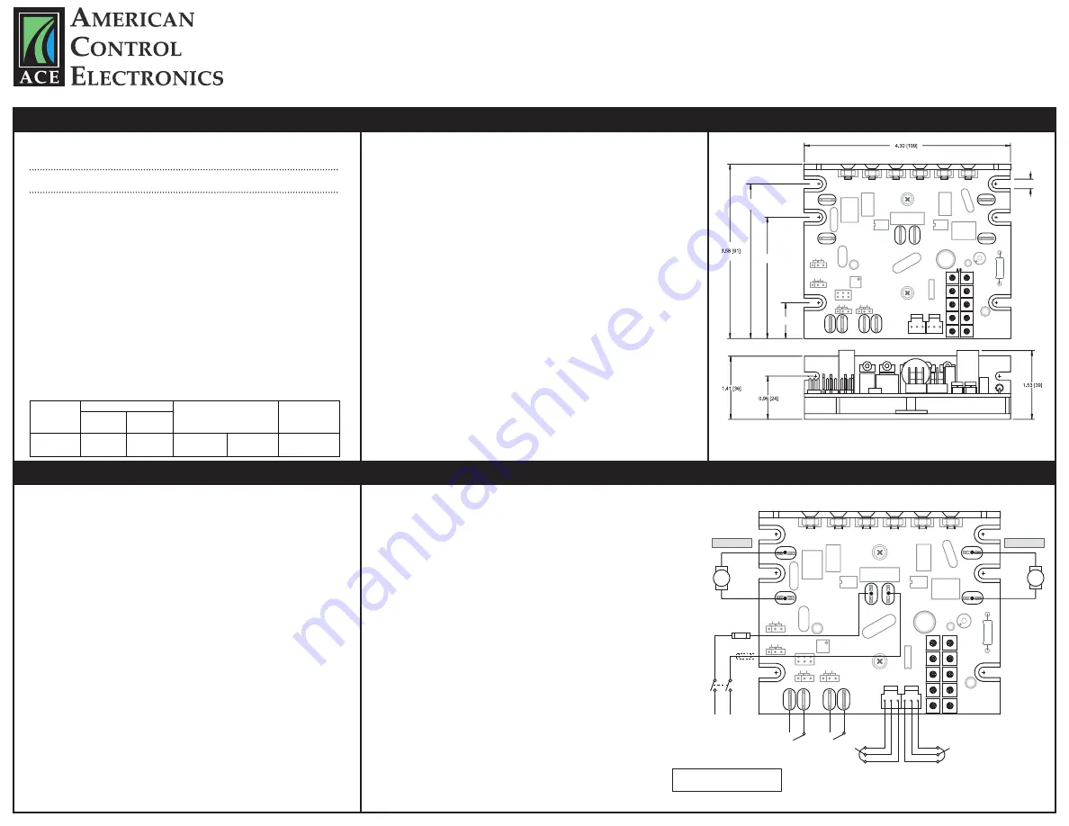
ALL DIMENSIONS IN INCHES [MILLIMETE
R
S]
Dimensions
S1
1
S
2
S
S2
S3
M
IN-SPEED
-MAX
IR COM
P
S3
L2
L1
A-/A
A+/A
1
ACC/DEC
CUR LIM
A -- INHIBIT -- B
J504
J505
J507
J506
A-B
IC503
IC502
J503
J502
C5
07
C5
08
180 90
C510
C506
C505
C503
D501
D502
U1
R503
R501
C15
Q504
Q503
Q502
R38
MOV502
C501
J501
Y501
C504
A- / B
A+ / B
M
TORQUE
SPEED
INDE
P.
RA
TIO
6 PLACES
.675 [17.2]
2.43 [61.7]
3.175 [80.7]
3.175 [80.7]
.186 [5]
180 90
Installation
Mounting
• Drive components are sensitive to electrostatic discharge. Avoid direct contact with the circuit
•
board. Hold the drive by the chassis or heat sink only.
• Protect the drive from dirt, moisture, and accidental contact.
• Provide sufficient room for access to the terminals and calibration trim pots.
• Mount the drive away from heat sources. Operate the drive within the specified ambient operating
•
temperature range.
• Prevent loose connections by avoiding excessive vibration of the drive.
• Mount the drive with its board in either a horizontal or vertical plane. Eight 0.19” (5 mm) wide slots
•
in the chassis accept #8 pan head screws. Fasten either the large base or the narrow flange of the
•
chassis to the subplate.
• The chassis should be earth grounded. Use a star washer beneath the head of at least one of the
•
mounting screws to penetrate the chassis surface and to reach bare metal.
Heat Sinking
The MTU400-11.5 requires an additional heat sink when the continuous armature current of either
motor is above 5 amps or the combined continuous output current is over 6.5 amps. Use ACE heat sink
kit part number HSK-0001. Use a thermally conductive heat sink compound (such as Dow Corning 340®
Heat Sink Compound) between the chassis and the heat sink surface for optimal heat transfer.
Wiring
Use 18 - 24 AWG wire for logic wiring. Use 14 - 16 AWG wire for AC line and motor wiring.
Shielding Guidelines
As a general rule, ACE recommends shielding of all conductors. If it is not practical to shield power
conductors, ACE recommends shielding all logic-level leads. If shielding of logic-level leads is not
practical, the user should twist all logic leads with themselves to minimize induced noise. It may be
necessary to earth ground the shielded cable. If noise is produced by devices other than the drive,
ground the shield at the drive end. If noise is generated by the drive, ground the shield at the end
away from the drive. Do not ground both ends of the shield.
Fusing
ACE drives require an external line fuse for protection. Use fast acting fuses rated for 250 VAC or
higher and 150% of the maximum armature current. Fuse the HOT leg of the AC line when using 115
VAC and both lines when using 230 VAC.
* NOTE: Do not add fuse to L2
unless input voltage is 230 VAC.
Line Input
Connect the AC line power leads to terminals L1 and L2. ACE recommends the use of
a double-pole, single-throw master power switch. The switch should be rated at a
minimum of 250 VAC and 200% of motor current.
Motors
Connect the DC armature leads of motor A to terminals A+/A and A-/A. If motor A does not
spin in the desired direction, power down the drive and reverse these connections.
Connect the DC armature leads of motor B to terminals A+/B and A-/B. If motor B does not
spin in the desired direction, power down the drive and reverse these connections.
Speed Potentiometers
Use 10K ohm, 1/4 W potentiometers for speed control. Connect the counter-clockwise
end of the potentiometer to S1, the wiper to S2, and the clockwise end to S3. If the
potentiometer works inversely of desired functionality, (i.e. to increase motor speed,
you must turn the potentiometer counterclockwise), power off the drive and swap
the S1 and S3 connections.
Inhibit
Short the INHIBIT terminals to coast the motor to zero speed. Open the INHIBIT
terminals to accelerate the motor to set speed. Twist inhibit wires and seperate them
from power-carrying wires or sources of electrical noise. Use shielded cable if the inhibit
wires are longer than 18 inches (46 cm). If shielded cable is used, ground only one end
of the shield to earth ground. Do not ground both ends of the shield.
Do not use the inhibit for emergency stopping.
Connections
POWER
LOGIC
S1
1
S
2
S
S2
S3
MIN
-SPEED-MAX
IR COM
P
S3
L2
L1
A-/A
A+/A
1
ACC/DEC
CUR LIM
A -- INHIBIT -- B
J504
J505
J507
J506
A-B
IC503
IC502
J503
J502
C507
C508
180 90
C510
C506
C505
C503
D501
D502
U1
R503
R501
C15
Q504
Q503
Q502
R38
MOV502
C501
J501
Y501
C504
A- / B
A+ / B
M
TORQUE
SPEED
INDE
P.
RA
TIO
180 90
LINE
VOLTAGE
115 / 230 VAC
MASTER
POWER
SWITCH
FUSE
MOTOR A
MOTOR B
CLOSE TO
INHIBIT DRIVE
FUSE*
SPEED POT A
OR
MASTER POT
SPEED POT B
OR
RATIO POT
A-B


