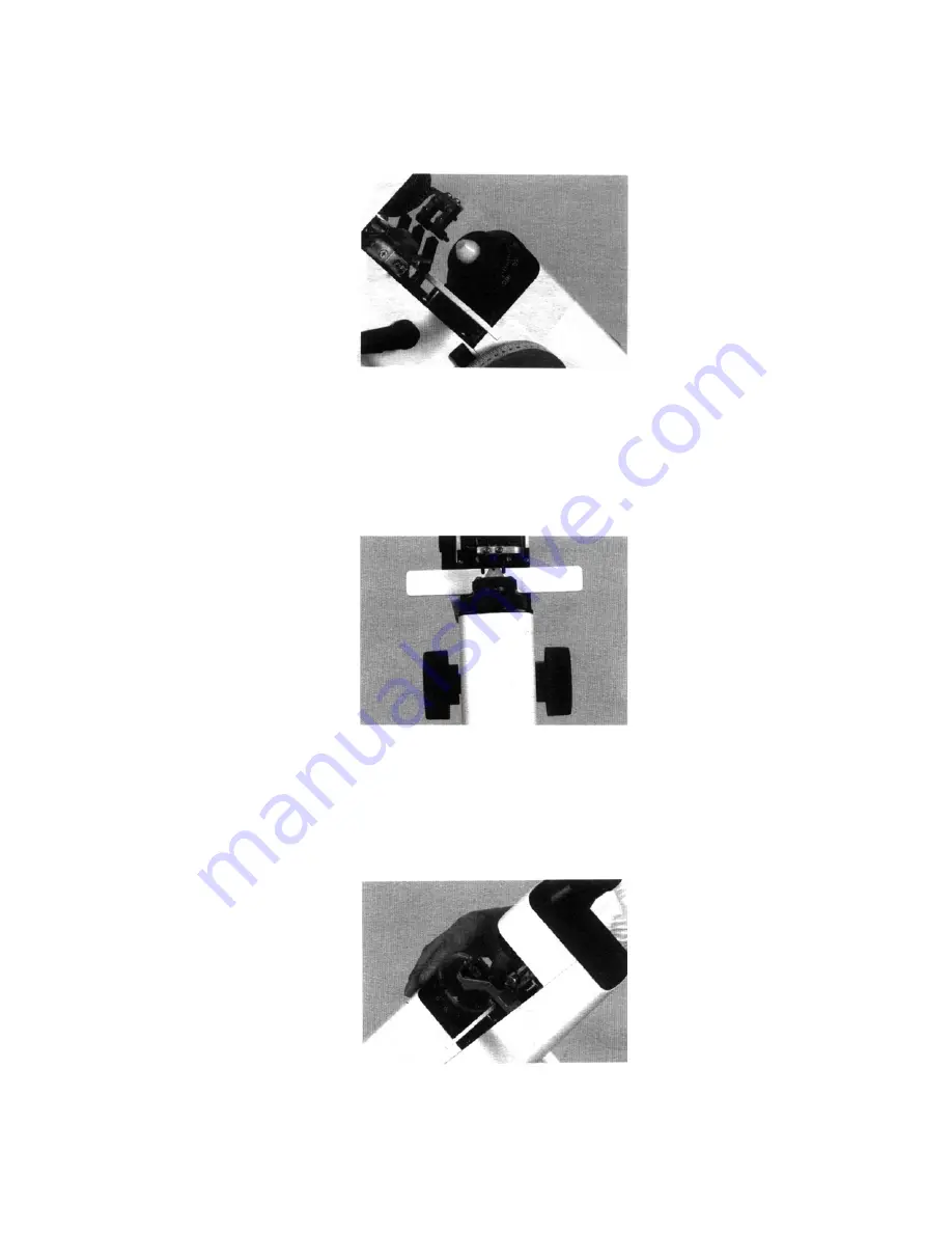
Objective Lens Bearing Seat (Fig. 10)
This while nylon part securely supports the surface of any shaped lens without damaging the lens surface.
The objective lens is shown below. There are three lock screws.
Fig. 10
Diopter Measuring Handwheels (Fig. 11)
The diopter measuring handwheels are located on either side of the lensometer. They can be rotated smoothly
and steadily to adjust the focus until the observer can clearly see the indication of the lens diopter through the
reading window.
Fig. 11
Astigmatism Axis Measuring Handwheel (Fig. 12)
This handwheel is used to measure and fix the axis of the cylindrical lens and the base angle of the prism lens.
Fig. 12
6


