


6
Technical data
Note Only use nozzles of identical type as supplied by manufacturer
Model
ARO40
Fuel type
35 sec gas oil class D visc 1.5E at 20˚C
Oil supply connection
RC
1
/
4
BSP Male
Heat input Gross
38kW
Heat input Nett
35.7kW
Flow rate Lts/Hr
3.6
Gals/hs
0.8
Nozzle size/Spray Angle
Danfoss 0.85 30S
Burner pump pressure
Bar
9
PSI
130
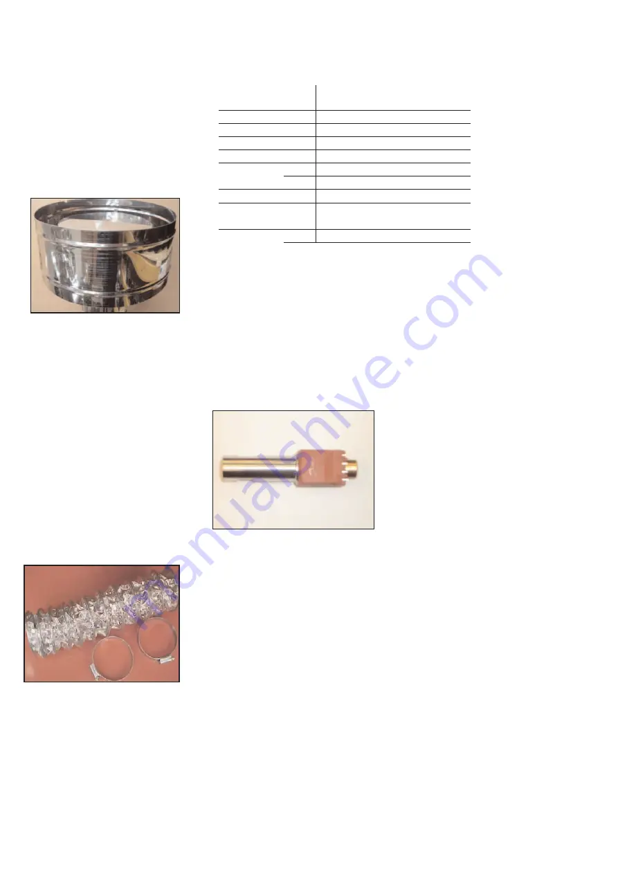
Flue details
Each heater must be individually flued.
Stainless steel twin wall flue is
recommended to minimise condensation.
The product must be used with a flue to
the outside.
Flue diameter 100mm (4”).
An approved terminal must be used.
7 Flue details
Maximum flue length is 4m (13ft).
Flue termination must be vertical.
Maximum bends : 2
8 Ventilation requirements
Permanent ventilation must be ensured.
Natural Ventilation
(Preferably at low level)
Up to and including 60kW: 4.5cm
2
/kW.
Over 60kW : 270cm
2
+ 2.25cm
2
/kW in
excess of 60kW total rated input.
Forced Ventilation
Minimum proven air flow is 2.35m
3
/h/kW
of total rated input.
9 Ducted air for polluted/dusty
atmospheres
A fresh air ducted inlet is available as an
option to prevent ingress of process dust,
chlorinated vapours etc. If installation is in
a potentially polluted atmosphere the
installer must consider prior to installation,
the requirement for this option. The duct-
ed air inlet is to be connected between the
burner and a suitable 100mm ducted air
feed pipe to outside.
10 Oil type and supply details
Pre heater
In cold climates with continued sub zero
temperature, consideration must be given
to heating and lagging of the oil tank.
Insulate external pipework to reduce the
potential of freezing.
To prevent freezing ensure winter grade
fuel is used during the winter.
If temperatures are likely to fall below
-4˚C. A burner with pre- heater should be
used to stop waxing of the oil.
The oil supply line shall be sized to ensure
that the required flow rate at the burner is
achieved at all times.
Oil lifter installation see Fig 7. page 7
(Single Burner). Lift pump/installation. See
Fig 8. page 7. (Multiple Burner).
It is recommended that isolation valves are
provided to facilitate servicing. Oil storage
tanks must be installed outside the
building in accordance with the
regulations in force.
• A ring main pressure of min 0.5 to 1.5
bar gauge must be used.
• Use pressure regulating valves as
appropriate. The flexible oil line must
be used to allow for expansion of the
heater.
Fire valve
A fire valve (operating temperature 70˚C)
must be utilised to sense each burner
installed. The oil shut off valve should be
sited externally of the building. (See Fig 7
and 8. Page 7 on the feed from the
storage tank.
Lift Pumpset
Where a lift pump set (Part No 200140) is
used it is recommended that the pump is
wired into the control panel to give
continuous oil circulation. This will assist
in preventing waxing of the oil during the
winter period and also ensure a
continuous delivery of oil to the burners.
Flexible oil lines
Where the flexible oil lines connect
between the fixed oil supplies and burner,
do not allow lines to become stretched or
stressed allow ‘Easy’ bends, which will
compensate for expansion of the heater.
Pre heater