Maintenance are care
54
GH HH
Super SMARTCUT BAF0009.3 05.17
Страница 1: ...1800 SUPER GH 2100 SUPER HorseHopper SmartCut HH 1800 SUPER HH 2100 SUPER MG5084 BAF0009 3 05 17 Printed in France Please read and follow this op erating manual before putting the machine into operati...
Страница 2: ...f The person concerned would not only harm himself but also make the mistake of blaming the machine for the reason of a possible failure instead of himself In order to ensure good success one should g...
Страница 3: ...AMAZONE S A FORBACH 17 rue de la Verrerie BP 90106 F 57602 Phone Fax E mail Forbach France 33 0 3 87 84 65 70 33 0 3 87 84 65 71 forbach amazone fr Spare part orders Spare parts lists are freely acce...
Страница 4: ...hine into operation Only after careful reading will you be able to benefit from the full scope of your newly purchased machine Please ensure that all the machine operators have read this operating man...
Страница 5: ...and other labels 21 2 14 Dangers if the safety information is not observed 22 2 15 Safety conscious working 22 2 16 Safety information for users 23 2 16 1 General safety and accident prevention inform...
Страница 6: ...Mowing 43 6 3 Scarifying 44 6 4 Mulching 46 6 5 Collecting 46 6 6 Emptying the hopper 46 7 Adjusting the cutting height 48 7 1 Front roller option 50 8 Cleaning the machine 51 9 Maintenance are care...
Страница 7: ...fied in the operating manual are always viewed in the direction of travel 1 3 Diagrams used Instructions for action and reactions Tasks to be carried out by the user are presented as numbered in struc...
Страница 8: ...ble state To replace damaged warning symbols If you still have queries please contact the manufacturer Obligations of the user Before starting work anyone charged with working with on the ma chine is...
Страница 9: ...e These shall be available to the operator at the latest on the comple tion of the contract Guarantee and liability claims for damage to peo ple or goods will be excluded if they can be traced back to...
Страница 10: ...n imme diate death or serious physical injury WARNING Indicates a medium risk which could result in death or extreme ly serious physical injury if not avoided If the instructions are not followed then...
Страница 11: ...egularly 2 4 Safety and protection equipment Before each commissioning of the machine all the safety and protec tion equipment must be properly attached and fully functional Check all the safety and p...
Страница 12: ...y 2 Instructed persons are those who have been instructed in their assigned tasks and in the possible risks in the case of improper behaviour have been trained if necessary and have been in formed abo...
Страница 13: ...ydraulic system against unintentional start up Carefully fix and secure larger subassemblies to lifting gear when carrying out replacement work Regularly check that bolted connections are firmly secur...
Страница 14: ...t the operating permit retains its validity in accordance with national and international regulations If you use wear and spare parts from third parties there is no guarantee that they have been desig...
Страница 15: ...symbol consists of two fields Field 1 is a symbol describing the danger surrounded by triangular safety symbol Field 2 is a symbol showing how to avoid the danger Warning symbols explanation The colum...
Страница 16: ...from hands or arms Never open or remove protective equipment from chains or belt drives while the tractor engine is running and the PTO shaft is connected hydraulic drive is engaged or the ground whe...
Страница 17: ...and understand the operating manual safe ty information before starting up the machine MD 096 Danger of infection to the whole body from liquids escaping at a high pressure hydraulic fluid This dange...
Страница 18: ...raulic system only from the designated workstation never from a location in the stroke ar ea between tractor and machine MD 100 This symbol indicates lashing points for fastening slinging gear when lo...
Страница 19: ...ervicing and maintaining in the appropriate chapter of the operating manual MD 114 This symbol indicates a lubrication point MD 115 The maximum operating pressure of the hydrau lic system is 200 bar M...
Страница 20: ...in or caught by unprotected moving machine parts as a re sult of missing safety devices This hazard can cause extremely serious inju ries including the loss of body parts Close protective equipment w...
Страница 21: ...0009 3 05 17 21 2 13 1 Positioning of warning symbols and other labels Warning symbols The following diagrams show the arrangement of the warning symbols on the machine MD076 MD078 MD078 MD075 MD123 M...
Страница 22: ...through non secured working areas Failure of important machine functions Failure of prescribed methods of maintenance and repair Danger to people through mechanical and chemical impacts Risk to envir...
Страница 23: ...h the attached machine In so doing take your personal abilities into account as well as the road traffic visibility and weather conditions the driving characteristics of the tractor and the connected...
Страница 24: ...may not release themselves when lowered Also ensure that uncoupled machines are stable Use of the machine Before starting work ensure that you understand all the equip ment and actuation elements of...
Страница 25: ...must guarantee the prescribed brake delay for the loaded vehicle combination tractor plus connected machine Check the brake power before moving off When turning corners with the machine connected take...
Страница 26: ...y the parking brake Take out the ignition key Have the hydraulic hose line checked at least once a year by a specialist for proper functioning Replace the hydraulic hose line if it is damaged or worn...
Страница 27: ...cal system will be destroyed danger of fire Ensure that the battery is connected correctly firstly connect the positive terminal and then connect the negative terminal When disconnecting the battery d...
Страница 28: ...the EC Machin ery Directives 2006 42 EC and associated additional guidelines 3 3 Details required for enquiries When ordering special optional equipment and spare parts please always quote the machine...
Страница 29: ...intended use Any use which goes beyond these limits is not regarded as the in tended use The manufacturer is not liable for any damages which may result from such use The risk involved in such use is...
Страница 30: ...lubrication 5 Attaching and removing the machine at the tractor s rear three point linkage Before attaching the machine to the tractor make sure that the lateral setting of the three point linkage on...
Страница 31: ...gs Attach the PTO shaft to the tractor s universal joint shaft Cau tion make sure that the PTO shaft is the correct length other wise the tractor or the machine s angular gearbox may be dam aged when...
Страница 32: ...ith or without freewheel for tractors with max 40 HP output Walterscheid W 2400 with or without freewheel for tractors with outputs higher than 40 HP If you have a tractor without a double clutch for...
Страница 33: ...shaft tubes side by side and check whether the PTO shaft tubes provide a guaranteed sliding profile overlap of at least 40 of the LO both when the machine is lowered and raised 2 When pushed together...
Страница 34: ...when the tractor engine is running at low revs 5 3 Groundkeeper HorseHopper transmission input speed The gearbox on the Groundkeeper HorseHopper is equipped with a universal joint shaft connection The...
Страница 35: ...k on the implement for the markings that illustrate the respective hydraulic function The tractor control unit must be used in different types of activa tion depending on the hydraulic function Latche...
Страница 36: ...hydraulic hose lines WARNING Risk of crushing cutting being trapped or drawn in or impact through faulty hydraulic functions when hydraulic hose lines are incorrectly connected When coupling the hydr...
Страница 37: ...ydraulic hose lines 1 Swivel the actuation lever on the tractor control unit on the trac tor to float position neutral position 2 Unlock the hydraulic connectors from the hydraulic sockets 3 Protect t...
Страница 38: ...rom so called clip bolts 6 1 Fitting the mowing and scarifying tools There are 5 different tool arrangements as shown in table 11 If the mowing blades tab 11 A or scarifying blades tab 11 B have been...
Страница 39: ...ade 2 mm Scarifying blade 3 mm Wing blade long H77 ground Wing blade long H77 ground sharpened Wing blade long H60 ground Piece Piece Piece Pair Pair Pair Working width 1 80 m 100 pcs 100 pcs 100 pcs...
Страница 40: ...lip bolts must be checked regularly for wear Heavily worn tools must be promptly replaced Figs 8 1 2 and 8 1 3 show the limits of wear for the mounting brackets CAUTION The blades and the blade fasten...
Страница 41: ...erial dry conditions 100 scarifying blade Collecting Scarified material wet conditions 100 wing blade long H77 100 scarifying blade Mowing scarifying and collecting in one opera tion dry conditions Mo...
Страница 42: ...is accessed in the following manner Attach the machine to a tractor Open container to max position Turn off the tractor engine Hang in retaining hook Fig 6 1 5 Remove the screws for the intermediate h...
Страница 43: ...TO shaft speed of 540 rpm must be observed The hopper must be emptied in good time to ensure tidy collection If the container is too full this may cause a blockage in the vertical shaft above the roto...
Страница 44: ...cut short only the straight scarifying blades are fitted The combination of mowing and scarifying blades produces the best suction effect Therefore a combination of mowing and scarifying blades shoul...
Страница 45: ...l lead to the whole machine being damaged 2 Only one type of scarifying blade may be used Risk of imbal ance 3 If a high proportion of soil content is produced from scarify ing only fill the hopper to...
Страница 46: ...uction effect produced by the rotor the ma chine can also be used for collecting mowed grass or any other mate rial lying loose on the ground The material is then lifted up by air suc tion chopped to...
Страница 47: ...e embankment CAUTION Always drive with great care if the hopper is open The closing procedure for the hopper should take at least 8 seconds This closing speed can be adjusted via the integrated check...
Страница 48: ...he guide wheels is adjusted by removing and reposi tioning the distance sleeves fig 7 1 To adjust the wheels it is nec essary to raise the machine using the tractor s hydraulic system The lynch pins m...
Страница 49: ...3 05 17 49 Select the required working height via the height adjusting screw Fig 7 3 Tighten the clamping screw Fig 7 2 Care must be taken to ensure that the cage roller is equally adjusted on both si...
Страница 50: ...a special accessory for scarifying on une ven terrain It is fitted into the holders of the front guide wheels fig 7 1 1 To adjust the height of the machine it must be raised and the lynch pin and bolt...
Страница 51: ...wet grass which is also sometimes inter spersed with earth In such cases it is recommended to clean the rotor and the hopper intensively with a jet of water The rotor and hood can be accessed as foll...
Страница 52: ...vel in the angular gearbox The angular gearbox on the machine does not require lubrication servicing However the oil level must be checked at least once a year The inspection screw on the side of the...
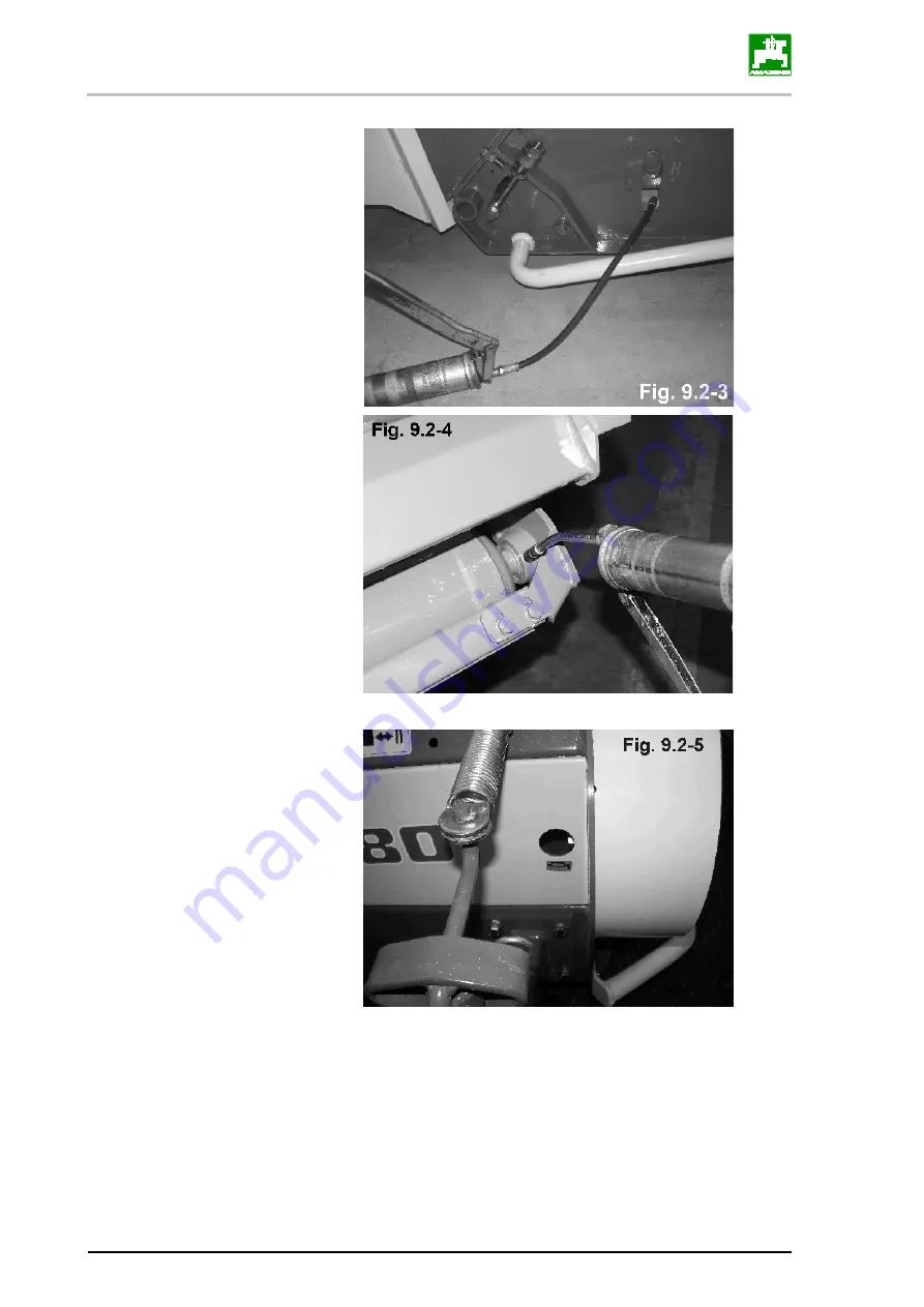
Страница 53: ...gularly lubricated with multipurpose grease Guide wheel fork bearing fig 9 2 1 Rotor bearings the V belt protection on the left hand side of the machine must be removed beforehand WAF 13 Fig 9 2 2 Rea...
Страница 54: ...Maintenance are care 54 GH HH Super SMARTCUT BAF0009 3 05 17...
Страница 55: ...machine is cleaned and sprayed with a suitable preservative Before recommissioning an authorised gar age should check that the overload clutch between the angular gear box and the belt drive is operat...
Страница 56: ...Gaste Germany Phone 49 5405 501 0 e mail amazone amazone de http www amazone de az S A FORBACH 17 rue de la Verrerie BP 90106 F 57602 FORBACH Cedex France Tel 33 0 3 87 84 65 70 Telefax 33 0 3 87 84 6...