Amazone AmaTron 4 Скачать руководство пользователя страница 72

7

Managing the customers

REQUIREMENTS

The job data is imported, see page 63 or the field
is created, see page 62

The job is created; see page 66 or imported with
the job data

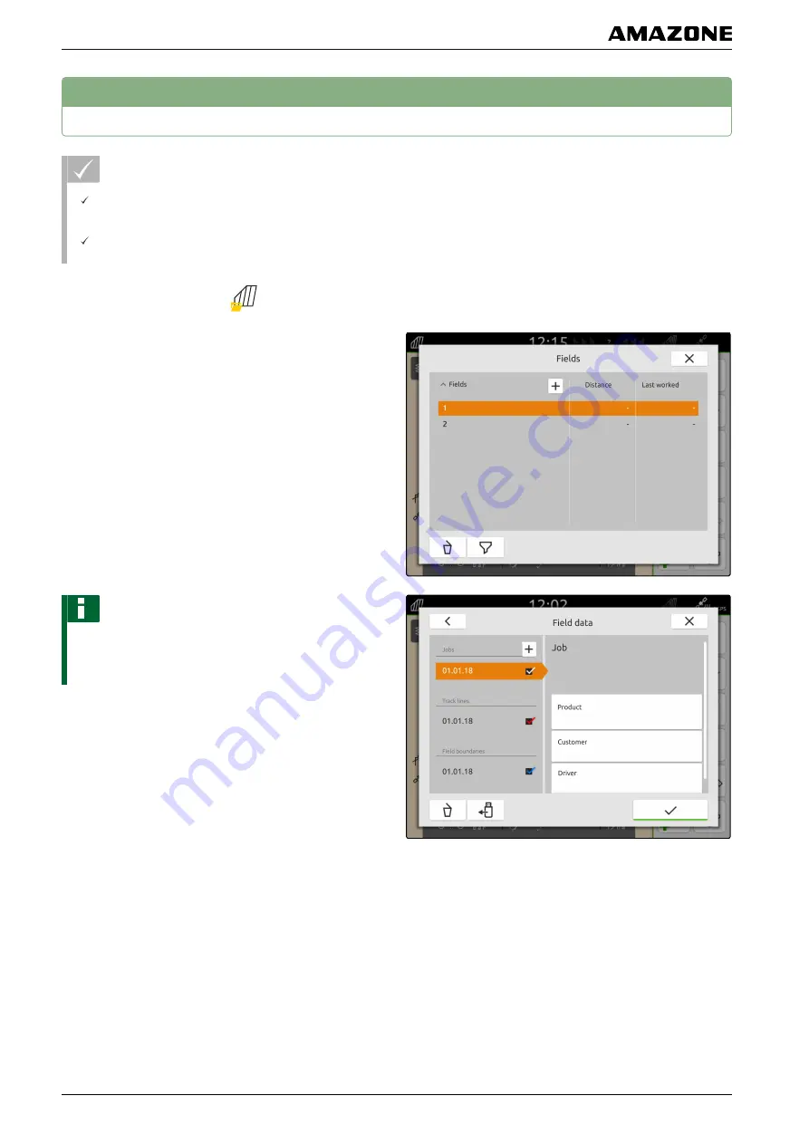
1. In the Work menu, select 

.

2. Select the field.

NOTE

To create a customer, a random job must be created
and selected. The created customers can then be
assigned to any job.

3. Select any job under 

"Jobs"

.

4. Select 

"Customer"

.

CMS-T-00000335-C.1

P | Working with documentation | Managing the customers


MG6010-EN-GB | G.1 | 13.12.2018

70

Содержание AmaTron 4

Страница 1: ...Operating instructions MG6010 EN GB G 1 13 12 2018 Control terminal AmaTron 4 This operating manual is valid from software version NW216 B Original operating instructions...

Страница 2: ......

Страница 3: ...ues 20 6 Enter text 21 F Entering the basic settings 22 1 Activating the dynamic button bar 22 2 Configuring the camera 23 3 Activating the ignition switch 23 4 Setting the date and time 24 5 Changing...

Страница 4: ...reating a new job 66 6 Managing products 67 7 Managing the customers 70 8 Managing drivers 71 9 Exporting ISO XML job data 73 Q Using part width section control 74 1 Overlap setting 74 1 1 Defining th...

Страница 5: ...X Using the Universal Terminal 103 Y Taking screenshots 104 Z Using the camera 105 Indexes 2 INDEX 106 TABLE OF CONTENTS MG6010 EN GB G 1 13 12 2018 3...

Страница 6: ...erved before initial operation of the implement 2 Before starting work also read and observe each section of the operating manual 3 Keep the operating manual available 4 Hand over the operating manual...

Страница 7: ...NT Indicates a risk for damage to the implement ENVIRONMENTAL INFORMATION Indicates a risk for environmental damage NOTE Indicates application tips and instructions for optimal use 2 3 Instructions Nu...

Страница 8: ...or Alternative instruction 2 Instruction 2 Instructions with only one action Instructions with only one action are not numbered but rather shown with a arrow Example Instruction Instructions without...

Страница 9: ...r opinion is important Dear reader our operating manuals are updated regularly Your suggestions for improvement help us to create ever more user friendly operating manuals Please send us your suggesti...

Страница 10: ...Installation instructions B GPS CMS T 00000302 B 1 B Installation instructions MG6010 EN GB G 1 13 12 2018 8...

Страница 11: ...AmaTron 4 overview C 1 Front view 1 2 3 4 5 6 7 8 9 10 CMS T 00001632 A 1 CMS T 00001633 A 1 C AmaTron 4 overview MG6010 EN GB G 1 13 12 2018 9...

Страница 12: ...trols 7 On Off button 8 Proximity sensor 9 Brightness sensor 10 Touch display 2 Connections 1 3 4 5 6 7 2 1 Top USB port 2 Rear USB port 3 Ethernet connection for service work 4 Connection for GPS sig...

Страница 13: ...e overview D 1 Main menu 1 Status bar 2 Display of the active implement and the active tractor 3 Application carousel CMS T 00000210 C 1 CMS T 00000234 B 1 D Operator interface overview MG6010 EN GB G...

Страница 14: ...2 Application carousel The application carousel 1 contains the following applications CMS T 00000254 B 1 D Operator interface overview Application carousel MG6010 EN GB G 1 13 12 2018 12...

Страница 15: ...rols for the connected implement AUX N assignment Configure connected AUX N input device Setup menu Configure AmaTron 4 Tractors and implements Configure tractors and implements Camera Show camera ima...

Страница 16: ...he tractor and implement 4 Compass 5 Define the maximum zoom level 6 Define the minimum zoom level 7 Symbols for tractor and implement 8 Degree of overlap 9 GPS speed 10 Implement information CMS T 00...

Страница 17: ...ion control 4 Create field boundary 5 No function 6 Create headland 7 No function 8 Create marking 9 Open field menu 10 GPS drift correction 11 Create new field 12 GPS switch settings 1 2 3 5 7 9 11 1...

Страница 18: ...1 Implement information 2 Function keys NOTE The display within the Universal Terminal depends on the connected implement CMS T 00000236 B 1 D Operator interface overview Universal Terminal MG6010 EN...

Страница 19: ...must be confirmed see page 98 To switch off the AmaTron 4 press and hold the on off button 1 1 2 Switching between the applications 2 1 Using the menu buttons 1 To open main menu press 1 2 To open th...

Страница 20: ...estures can be selected in the setup menu see page 27 IMPORTANT Risk of implement damage With a swiping gesture buttons of the implement controls can be accidentally actuated Start the swipe gesture a...

Страница 21: ...he desired position 3 To terminate the configuration touch the display underneath the information overview 4 Using the quick start menu The quick start menu contains keys for rapid access to the follo...

Страница 22: ...a numerical value must be entered a numeric keypad will be opened In addition calculator functions are available The executed calculations are shown above the value to the entered The valid value ran...

Страница 23: ...enter digits or special characters select 123 To call up other special characters select 1 2 Confirm the entry with or To cancel the entry touch the display above the numeric keypad CMS T 00000205 B 1...

Страница 24: ...utomatically hidden in the map view after 10 seconds When the user moves their hand on the display the button bar is shown again 1 In the Setup menu select Basic settings 2 Activate the dynamic button...

Страница 25: ...omatic reverse driving detection 4 To mirror the camera image select Mirror camera horizontally or Mirror camera vertically 3 Activating the ignition switch When the ignition switch is activated the A...

Страница 26: ...time 1 In the Setup menu select Basic settings Date and time 2 Enter the desired date under Date 3 Enter the desired time time format and time zone under Time CMS T 00001685 B 1 F Entering the basic s...

Страница 27: ...er Language 3 Select the desired decimal separator under Decimal separator 4 Select the desired system of units under System of units 6 Adjusting the volume 1 In the Setup menu select Basic settings C...

Страница 28: ...7 Setting the display brightness 1 In the Setup menu select Basic settings 2 Adjust the display brightness using the slider CMS T 00000221 C 1 F Entering the basic settings Setting the display bright...

Страница 29: ...lect Basic settings 2 Activate Touch display or deactivate 9 Activating swipe gesture applications With swipe gestures you can switch between the following applications Map view Camera image Universal...

Страница 30: ...tup menu select Basic settings Applications for swipe gestures 2 Activate the desired applications or deactivate F Entering the basic settings Activating swipe gesture applications MG6010 EN GB G 1 13...

Страница 31: ...on satellites send correction data to the receivers The correction data increase the accuracy REQUIREMENTS A100 A101 receiver is connected 1 In the Setup menu select GPS receiver 2 Select Configure GP...

Страница 32: ...ncludes the correction services EGNOS WAAS and MSAS For more information on this topic please consult the operating manual for the satellite receiver Without the correction mode the received signal is...

Страница 33: ...select the desired correction mode 5 If the GPS receiver should send the NMEA 2000 data to the CAN bus activate NMEA 2000 CAN 3 Resetting the GPS receiver to factory settings 1 In the Setup menu selec...

Страница 34: ...3 Select Factory settings 4 Confirm reset with G Setting up the GPS receiver Resetting the GPS receiver to factory settings MG6010 EN GB G 1 13 12 2018 32...

Страница 35: ...2 Under ISOBUS UT number enter the identification number for the Universal Terminal of the AmaTron 4 The AmaTron 4 has a clear identification number for the job documentation TC number If the job doc...

Страница 36: ...NE Licence management can be used to activate the 5 applications on the AmaTron 4 to be able to use these applications permanently The following table shows an overview of the functions that are activ...

Страница 37: ...matic part width section control with a maximum of 256 part width sections X Recording of the worked area ISOBUS or manually X X Creating field boundaries X X Automatic boom lowering X Virtual headlan...

Страница 38: ...ds X Show camera image X 1 In the Setup menu select License management In the list of applications the remaining period of use is displayed for each license or whether the application is activated or...

Страница 39: ...settings on the AmaTron 4 Implement management Deletes all created tractors and implements Documentation Deletes all job data Saved pools Deletes the saved views of the implement controls 2 Select the...

Страница 40: ...or towed whether the GPS receiver is installed on the tractor or on the implement whether the implement is self propelled REQUIREMENTS The ISOBUS implement is connected 1 In the main menu select 2 Se...

Страница 41: ...receiver relative to the attachment point 5 If the GPS receiver is installed on the implement enter the values for A and B under Implement geometry 2 Configuring non ISOBUS implements 2 1 Creating non...

Страница 42: ...elling 4 Enter the implement type and manufacturer The implement geometry includes the following values X1 distance between the attachment point and the application point X2 on towed implements distan...

Страница 43: ...th for each part width section can be entered separately The part width sections are numbered from left to right in the direction of travel 9 In the list of part width sections change the values for t...

Страница 44: ...becomes orange 4 Delete the implement with or Cancel with 5 Selecting implements If non ISOBUS implements are connected the implements must be selected so that the correct implement data can be loade...

Страница 45: ...1 In the main menu select 2 Select the desired implement The selected implement is marked with a checkmark K Configuring implements Selecting implements MG6010 EN GB G 1 13 12 2018 43...

Страница 46: ...ractor geometry data the position of the GPS receiver relative to the longitudinal axis rear axle and to the attachment point on the tractor are specified The geometry data is needed to correctly disp...

Страница 47: ...ce from the GPS receiver to the attachment point 8 Confirm with 3 Configuring the tractor sensors 3 1 Configuring wheel sensors If the implement does not have its own speed signal the implement contro...

Страница 48: ...the number of pulses per minute under Current value or To determine the number of pulses per minute follow the instructions on the display under Teach in pulses 3 2 Configuring radar sensors If the i...

Страница 49: ...der Source 7 If the radar sensor signal comes from a radar sensor enter the number of pulses per minute under Current value or To determine the number of pulses per minute follow the instructions on t...

Страница 50: ...connected implement through the NMEA2000 protocol activate Send signal 3 4 Configuring the PTO shaft sensor If the connected implement needs the PTO shaft speed the pulses per revolution can be set an...

Страница 51: ...he value for the correct PTO shaft speed under Pulses per revolution 3 5 Configuring the working position sensor 3 5 1 Configuring digital working position sensors 1 In the main menu select 2 Select t...

Страница 52: ...alues for the different positions must be taught in on the AmaTron 4 Moreover the switchover point between the upper and lower end position must be taught in on the AmaTron 4 1 In the main menu select...

Страница 53: ...luated as Working position on 11 Move the tractor lifting device between the lower and upper end position 12 Select Teach in switchover point 4 Renaming tractors 1 In the main menu select 2 Press and...

Страница 54: ...In the main menu select 2 select 3 Select the desired tractor The selected tractor name becomes orange 4 Delete with or Cancel with CMS T 00000306 C 1 L Configuring tractors Deleting tractors MG6010 E...

Страница 55: ...n be selected It is possible to toggle between the selected functions 1 To select implement functions for the button bar press and hold the button for the map view 1 1 A list with the connected implem...

Страница 56: ...ations see page 18 2 Showing and hiding the implement information In the map view the implement information is shown at the bottom edge of the screen The implement information can be shown or hidden a...

Страница 57: ...t again 5 Focusing on the vehicle symbol When the vehicle symbol is outside of the displayed map area the view can be focused on the vehicle symbol In the map view select 6 GPS drift correction GPS dr...

Страница 58: ...menu select 2 Move the map using the arrows or To enter a value by which the map should be moved tap the length specifications 3 Confirm with M Using the map view GPS drift correction MG6010 EN GB G 1...

Страница 59: ...Activate Warnings about field boundaries obstacles or deactivate 2 Configuring the driving direction detection The driving direction detection ensures that the tractor symbol does not turn around whe...

Страница 60: ...ving direction detection 3 Automatically creating a safety zone If this function is activated a safety zone is automatically created inside a field boundary NOTE This function is only available for IS...

Страница 61: ...eed above 3 km h The zoom levels can be manually adjusted in the map view 1 In the Work menu select Basic settings 2 Activate Autozoom or deactivate 3 When autozoom is activated set the distance at wh...

Страница 62: ...oom levels can be adjusted at any time 5 Defining the map layers The following layers can be shown or hidden on the map Coordinate network Worked area Application map 1 In the map view select 2 Select...

Страница 63: ...r job data If a field has been worked and the current recording is available a new field must be created on the AmaTron 4 to be able to work a different field The recordings include the following data...

Страница 64: ...wing data is automatically saved with the field Field boundaries Track lines Obstacles Headlands Jobs cab be assigned to a field Products the customer and driver can be assigned to a job 1 In the Work...

Страница 65: ...r data Field data Field data Field boundaries Track lines Obstacles Headlands Application maps REQUIREMENTS ISO XML job data are saved as an XML file with the name Taskdata in the Taskdata folder in t...

Страница 66: ...the following data Jobs Field boundaries Track lines Application maps 3 To load a job together with the field set the checkmark for the desired job 4 To load track lines together with the field set t...

Страница 67: ...d the field and the selected data are shown on the map 4 Importing field data from a shape file Shape files that are saved to a USB flash drive can be displayed and the contained field data can be imp...

Страница 68: ...Confirm entries with The selected application maps are included in the field data under Jobs The selected field boundaries are included in the list of field boundaries 5 Creating a new job When a fiel...

Страница 69: ...67 Customer see page 70 Driver see page 71 6 Managing products REQUIREMENTS The job data is imported see page 63 or the field is created see page 62 The job is created see page 66 or imported with th...

Страница 70: ...job under Jobs 4 Select Product On the left side the setpoint receivers of the connected implement are listed 5 Select the desired setpoint receiver 6 Under Products select Configuration P Working wi...

Страница 71: ...ired products under Products The selected products are marked with a checkmark 12 Confirm with The selected products are assigned to the job and the setpoint receiver of the implement 13 To change the...

Страница 72: ...r imported with the job data 1 In the Work menu select 2 Select the field NOTE To create a customer a random job must be created and selected The created customers can then be assigned to any job 3 Se...

Страница 73: ...tomer The selected customer is marked with a checkmark 9 Confirm with 8 Managing drivers REQUIREMENTS The job data is imported see page 63 or the field is created see page 62 The job is created see pa...

Страница 74: ...job must be created and selected The created driver can then be assigned to any job 3 Select any job under Jobs 4 Select Driver 5 To create a new driver select 6 Enter the driver data 7 Confirm with...

Страница 75: ...as ISO XML job data and saved to a USB flash drive REQUIREMENTS USB flash drive is inserted 1 Open the quick start menu 2 select ISO XML The job data is saved in a folder on the USB flash drive The fo...

Страница 76: ...mes can be compensated which can be different depending on the implement The overlap in the direction of travel can be set separately for switching the part width sections on and off NOTE If a gap is...

Страница 77: ...off 6 Enter a value between 1 000 cm and 1 000 cm 7 Confirm with 1 2 Defining the degree of overlap The degree of overlap defines the percent by which a part width section can protrude over a boundar...

Страница 78: ...before any overlap occurs 50 The part width sections are switched off when they half protrude over a boundary 100 The part width sections are switched off when they fully protrude over a boundary Q U...

Страница 79: ...witched off Overlap tolerance prevents that the outer part width sections are constantly switched on and off when they touch on boundaries during parallel driving Boundaries for the overlap tolerance...

Страница 80: ...at the field boundary defines how far the outer part width sections can protrude over the field boundary before they are switched off Overlap tolerance at the field boundary prevents the outer sectio...

Страница 81: ...f the worked area Worked areas are shown in green in the map view The recordings include the following data Worked area Field boundaries Obstacles Headlands Track lines REQUIREMENTS GPS signal availab...

Страница 82: ...n switched on manually Green Part width section switched off via automatic part width section control Orange Part width section switched on via automatic part width section control Green Part width se...

Страница 83: ...rol switch all of the part width sections off using the implement controls or Stop or When the part width sections of the connected implement are switched manually select in the Work menu CMS T 000002...

Страница 84: ...the field boundary The worked area and the remaining area result from the field size REQUIREMENTS Completely work the field edge In the Work menu select The field boundary is laid around the worked ar...

Страница 85: ...ndaries 1 Tap on the field boundary 2 To rename the field boundary select or To delete the field boundary select CMS T 00000308 B 1 R Managing the field boundaries Editing field boundaries MG6010 EN G...

Страница 86: ...NOTE When the first track line is laid on the field boundary the second track line lies one working width away from the field boundary inside the field 3 If the first track line should be laid on the...

Страница 87: ...been created the headlands are shown as a grey area inside the field boundary NOTE To be able to start the application spreading within the headlands and use the track lines inside the headlands the...

Страница 88: ...rning is only issued if warnings are activated in the settings see page 57 The map is only zoomed if autozoom is activated see page 59 1 In the Work menu select An obstacle symbol is shown on the map...

Страница 89: ...5 If the obstacle symbol should be deleted select 6 To set the obstacle symbol tap on any spot on the map T Marking obstacles MG6010 EN GB G 1 13 12 2018 87...

Страница 90: ...supports the driver in staying on track The triangular symbols on the light bar light up when the track line deviation exceeds the entered value 1 1 In the Work menu select Parallel driving Light bar...

Страница 91: ...e that is laid between 2 points Smoothed contour Curved track line that is recorded while driving between 2 points The contours will be automatically smoothed 1 In the Work menu select Parallel drivin...

Страница 92: ...et on the vehicle position 3 Drive to the end of the row 4 select The end point of the track line is set on the vehicle position Other track line are added 2 2 Creating smoothed contours REQUIREMENTS...

Страница 93: ...added 3 Creating beds To create beds certain track lines can be highlighted The highlighted track lines show the row in which the worked area must be travelled to create a bed of the desired size The...

Страница 94: ...ing travel the light bar 1 shows the deviation of the vehicle from the driven track line in centimetres When the track deviation reaches the set value a triangular symbol beside the centimetre specifi...

Страница 95: ...e 19 Track lines are created see page 90 Light bar sensitivity is defined see page 88 To keep the vehicle on the track steer the vehicle by the displayed distance towards the track line U Parallel dri...

Страница 96: ...reached The value for the time of the lowering procedure must be determined manually The correct timing of the automatic boom lowering function depends on the following factors Forward speed Tractor e...

Страница 97: ...Automatic boom lowering 2 Activate Automatic boom lowering 3 Under Delay for boom lowering enter the duration of the lowering procedure in seconds 4 Confirm with V Using automatic boom lowering MG601...

Страница 98: ...s can be actuated with the AUX N input device NOTE Only AUX New input devices can be assigned with functions using the AmaTron 4 REQUIREMENTS AUX N input device is connected 1 In the main menu select...

Страница 99: ...are shown underneath With these keys the implement functions and the terminal functions can be opened 3 Open the implement functions or terminal functions 4 Select a function from the list The select...

Страница 100: ...s automatically opened 1 Check the AUX N assignment 2 If the AUX N assignment should be changed see page 98 or If the AUX N assignment is ok confirm with 2 2 Changing the AUX N assignment 2 2 1 Changi...

Страница 101: ...n from the list A list of available AUX N input devices will be shown 3 Select the desired AUX N input device An overview of available buttons will be shown 4 Select the desired button The selected bu...

Страница 102: ...AUX N assignment using the input list all of the available buttons are listed on the left side These buttons can be assigned to functions 1 If the buttons are not listed on the left side select 2 Sel...

Страница 103: ...lect the desired function The selected function is shown beside the button 5 Confirm with In the overview the button is assigned to the selected function 6 Assign other functions or W Configuring AUX...

Страница 104: ...3 Deleting the AUX N assignment 1 In the function list or input list select 2 Select the desired functions 3 Confirm with CMS T 00000364 B 1 W Configuring AUX N input devices Managing preferred assign...

Страница 105: ...ons corresponds to the representation of the keys on the user interface 1 To open the Universal Terminal Press the button for the Universal Terminal 1 2 To select the implement controls to be toggled...

Страница 106: ...ash drive as a graphic file The file name is composed of the current date and time REQUIREMENTS USB flash drive is inserted Press and hold the main menu button 1 1 A camera symbol is shown on the disp...

Страница 107: ...4 can show images from a connected camera REQUIREMENTS Camera is connected Camera is configured see page 23 In the main menu select The camera image is displayed CMS T 00000323 C 1 Z Using the camera...

Страница 108: ...modelling see Configuring non ISOBUS implements 40 Changing the implement type see Configuring non ISOBUS implements 40 Changing the system of units 25 Configuring the implement see Configuring non IS...

Страница 109: ...Jobs creating 66 exporting 19 importing 63 L Language changing 25 Lightbar 88 M Managing licenses 34 Map Overview 14 Map view opening 12 Overview 14 Menu buttons 17 N Non ISOBUS implement configuratio...

Страница 110: ...ode 19 T Track guidance enabling 34 using 88 Tractor creating 44 Sensors configuration 45 Tractors and implements Show menu 12 U Universal Terminal displaying 12 Overview 16 UT 16 V Variable rate cont...

Страница 111: ...AMAZONEN WERKE H DREYER GmbH und Co KG Postfach 51 D 49202 Hasbergen Gaste Germany Telefon 49 0 5405 501 0 E Mail amazone amazone de Internet www amazone de...

Отзывы: