


9
All ductwork exposed to the outdoors must include a weath-
erproof barrier and adequate insulation.
A duct system should be installed in accordance with Stan-
dards of the National Board of Fire Underwriters for the
Installation of Air Conditioning, Warm Air Heating and Ven-
tilating Systems. Pamphlets No. 90A and 90B.
The warm air supply duct from the unit through a wall
fabricated of combustible material may be installed without
clearance. However, minimum clearances for the unit must
be observed as shown in Specification Sheet.
The outlet duct should be provided with an access panel.
This access should be large enough to inspect the air
chamber downstream from the heat exchanger for any
smoke or combustion gas leaks. A cover should be tightly
attached to prevent air leaks.
For horizontal airflow, duct flange dimensions on the unit are
shown in Specification Sheet.
For vertical airflow, the ductwork should be attached to the
roof curb prior to installing the unit. Ductwork dimensions
are shown in the roof curb installation manual.
If desired, supply and return duct connections to the unit
may be made with flexible connections to reduce possible
unit operating sound transmission.
FILTERS
CAUTION
To prevent property damage due to fire and
loss of equipment efficiency or equipment
damage due to dust and lint build up on
internal parts, never operate unit without
an air filter installed in the return air system.
Even though a return air filter is not supplied with this unit,
there must be a means of filtering all return air.
Refer to Specification Sheet provided with unit for filter size
information.
If using the Over/Under Transition Kit, the filter(s) may be
located in the return air duct(s) or return air filter grille(s).
Filters installed external to the unit should be sized in
accordance with their manufacturer recommendations. A
throwaway filter must be sized for a maximum face velocity
of 300 feet per minute.
FILTER INSTALLATION
Important: When installing a filter, the air flow arrows on the
filter must point at the indoor blower.
VII. Venting
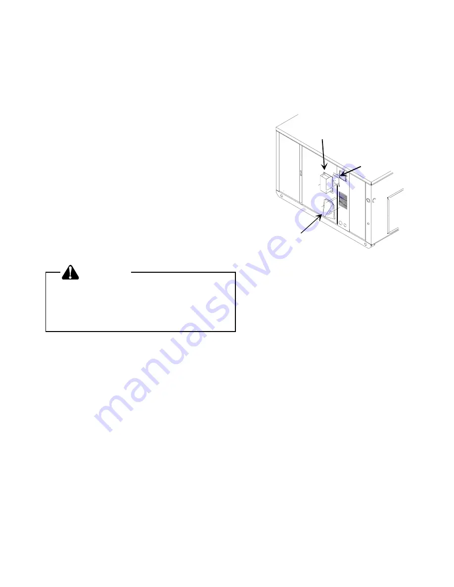
FLUE HOOD AND AIR INLET HOOD INSTALLATION
Install the flue hood and air inlet hood prior to operation of the
unit. See Figure 8.
To install the flue hood cover:
1. Remove the flue hood and bug screen from inside the
heating compartment.
2. Attach the flue hood and screen with the sheet metal
screw provided.
To install the air inlet hood:
1. Remove hood from the heating compartment.
2. Attach hood by using the supplied sheet metal screws.
Flue Hood
Air Intake Hood
Screen
Figure 8
Air Inlet Hood and Flue Hood
VENTING
NOTE: Venting is self-contained. Do not modify or block.
VIII. Condensate Drain
CONDENSATE DRAIN CONNECTION
This unit has a built in trap - no external trap is required.
To avoid double trapping and an overflowing drain pan, soft
plastic drain lines are not recommended.
IX. Heating Sequence of Operations
NORMAL SEQUENCE OF OPERATION - HEATING
1. Thermostat calls for heat. The combustion blower is
immediately energized.
2. The pressure switch contacts transfer.
3. The ignitor is energized and pilot gas begins to flow.
4. After pilot flame is proven, the main valve is energized
and the pilot will light the main burners.
5. The control checks the signal from the flame sensor.
Gas flow will continue only if a proper signal is present.
As soon as pilot flame is proven, the ignitor is de-
energized.
6. The unit will continue to fire for 30 seconds. The fan
control will then start the main circulating air blower.
7. The unit will deliver heat to the conditioned space until
the thermostat is satisfied.