SERVICING
42
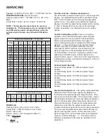
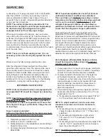
Checking Reversing Valve and Solenoid
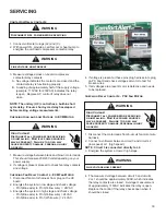
Occasionally the reversing valve may stick in the heating or
cooling position or in the mid-position.
When stuck in the mid-position, part of the discharge gas
from the compressor is directed back to the suction side,
resulting in excessively high suction pressure. An increase
in the suction line temperature through the reversing valve
can also be measured. Check operation of the valve
by starting the system and switching the operation from
COOLING to HEATING cycle.
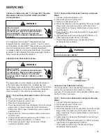
If the valve fails to change its position, test the voltage
(24V) at the valve coil terminals, while the system is on the
COOLING cycle.
All heat pumps and communicating heat pumps wired
in legacy
- If no voltage is registered at the coil terminals,
check the operation of the thermostat and the continuity
of the connecting wiring from the “O” terminal of the
thermostat to the unit.
Communicating heat pumps only
- Check voltage
(24VAC) at the non-insulated terminal E22 on the UC
control board (RVS on silkscreen) and “C” terminal on the
7-pin or 4-pin connector on the UC control
If voltage is registered at the coil, tap the valve body lightly
while switching the system from HEATING to COOLING,
etc. If this fails to cause the valve to switch positions,
remove the coil connector cap and test the continuity of
the reversing valve solenoid coil. If the coil does not test
continuous - replace it.
If the coil test continuous and 24 volts is present at the coil
terminals, the valve is inoperative - replace it.
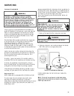
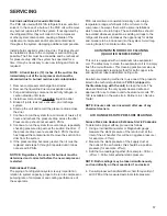
Testing Defrost Control
Legacy Models:
Communicating Units:
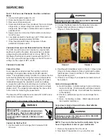
To check the defrost control for proper sequencing,
proceed as follows: With power ON; unit not running.
1. Set thermostat to call for heating.
2. Press
TEST
and
RECALL
buttons simultaneously for
approximately 3 seconds, then release them. System
should go into defrost immediately.
3. Using VOM check for voltage across terminals “C & O”.
Meter should read 24 volts (skip this step if system a
fully communicating system)
4. Visually inspect to see that the frost is gradually melting
on the coil and the compressor is running.
5. Using VOM check for voltage across “W2 & C” terminals
on the board. You should read 24 volts.
6. If not as above, replace control board.
7.
Set thermostat to off position and disconnect power
before removing any jumpers or wires.
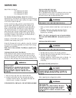
Testing Temperature Sensors
(Communicating Ready Models Only)
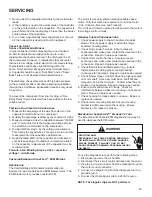
The ASXC and DSXC
communicating
air conditioner
models are factory equipped with an outdoor air
temperature (OAT) sensor.
The ASZC and DSZC
communicating
heat pump models
are equipped with both an outdoor air temperature (OAT)
sensor and an outdoor coil temperature (OCT) sensor. The
OAT provides the balance point temperature in heat pump
systems (air handler w/electric heat + heat pump) and dual
fuel systems. The OCT sensor provides the outdoor coil
temperature and is used in determining defrost cycles.
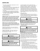
T, °F RW@T T, °F RW@T T, °F RW@T T, °F RW@T T, °F RW@T
-40
336,000
5
72,940
50
19,903
95
6,530
140
2,488
-31
242,700
14
55,319
59
15,714
104
5,327
149
2,083
-22
177,000
23
42,324
68
12,493
113
4,370
158
1,752
-13
130,400
32
32,654
77
10,000
122
3,603
167
1,480
-4
97,060
41
25,396
86
8,056
134
2,986
176
1,255
Ohm Reading of Communicating Outdoor Unit Sensors
Содержание ASXC16
Страница 4: ...PRODUCT IDENTIFICATION 4 ...
Страница 5: ...PRODUCT IDENTIFICATION 5 ...
Страница 70: ...SERVICING 70 PCBHR104 PCBHR105 ...


