


Timekeeper™
Users Manual
01/11/20
All segments ON test.
Press the Test button again to turn all segments on. Verify that all segments are lit. Also verify that either the decimal
points or colons are lit depending on hardware configuration.
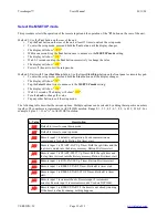
Input signal test.
Press the Test button again to enable the input signal test. Press each of the buttons, Activate each of the remote inputs.
Turn the knob both clockwise and counterclockwise. Numeric values should appear on the display as shown in the
following table. Two dashes will scroll across the display along with some values depending on the state of the various
inputs.
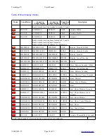
Display Value
Description
A
Button 1
B
Button 2
C
Button 3
D
Button 4
E
Button 5
F
Button 6
G
Button 7
H
Button 8
0
Remote Input 1
1
Remote Input 2
2
Remote Input 3
3
Remote Input 4
4
Rotary Encoder Knob or button A
5
Rotary Encoder Knob or button B
6
50Hz/60Hz Sync signal detected.
7
32,768Hz Internal Oscillator detected.
Normal operation.
The display should show “
--7
”, to indicate that the internal crystal is functioning or, “
--67
”, to
indicate that the internal crystal is functioning and 50Hz/60Hz Sync signal detected.
Example with button pressed.
If the display shows “
--63A
”, this indicates that Button 1 is pressed, Remote Input 1
is active and 50Hz/60Hz Sync signal detected.
VERSION=5C
Page 14 of 33


