background image

Timekeeper™

Users Manual

01/11/20

Rear panel buttons.

Your display may have none, one or two rear panel buttons. If your display has one rear panel button, it will be the 

Test/Configuration

 button.

Press the 

Test/Config

 button to display one of several test patterns.

Press and hold the 

Test/Config

 button to enter the configuration mode.

If your display does not have any rear panel buttons. You will still be able to make configuration changes. 

Press and hold the 

Start

 button until the display changes.

Press and hold the 

Start

 button again until the display changes.

You are now in the configuration mode.

If your display has two rear panel buttons, Button one will be the 

Test/Configuration

 button. Button two will be the 

B


button.

Press the 

Test/Config

 button to display one of several test patterns.

Press and hold the 

Test/Config

 button to enter the configuration mode.

Press the 

B

 button to enter the learn mode if a wireless keyfob receiver is installed. The 

B

 button is also used 

to decrement a value while in setup mode.

If your display has a built in battery and battery charger, in addition to the normal functions, these buttons will also 
perform the power ON and power OFF functions of the display.

Press and hold the 

Power ON/Test/Config

 button to turn the power on.

Press and hold the 

Off/B

 button to turn the power off.

Testing the unit.

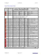
Pressing the Test button successively advances through each of several diagnostic tests. These tests verify the operation
of the unit. Each press of the test button selects on of the following displays.

Scrolling Hello Message.

Segment Test Pattern.

All segments ON.

Input signal test.

Scrolling Hello Message.

Press the Test button to display the scrolling "Hello" message. This message is also sent on the serial port. Observe that
the message “Hello” scrolls across the display every few seconds.

Segment Test Pattern.

Press the Test button again to display the segment test pattern sequence. Observe the display. The segments should 
light in the sequence as described below.

segment a on;
segment a-b on;
segment a-b-c on;
segment a-b-c-d on;
segment a-b-c-d-e on;
segment a-b-c-d-e-f on;
segment a-b-c-d-e-f-g on;
segment a-b-c-d-e-f-g-dp on;

VERSION=5C

Page 13 of 33

www.alzatex.com

Содержание Timekeeper F Series

Страница 1: ...uts and or a serial communication port Optional remote button modules may be used to control the timer display Applications Production Monitoring and Production Control Sporting Events of all kinds Take a number Systems Days since last accident display Count down clocks Public Speaking events Master Clock Systems And many others TMR221B TimeKeeperTM with 8 buttons knob and LED display KP219A RF2 w...

Страница 2: ...IOUS and RESET buttons The unit also has remote inputs for external buttons Range 0 to 999 999 Tallye Counter Wigits machine operations game scores or anything you may want to count may be counted The unit can be configured with UP DOWN and RESET buttons The unit also has remote inputs for external buttons or for connecting to a machine for automatic operation Range 0 to 999 999 Remote Terminal Th...

Страница 3: ...em Also select the desired count up down mode and beeper mode Press and hold the START button until the display changes The display will show FF Press and hold the RESET button until the display blinks to save the timer preset time green and yellow warning times timer count up down mode beeper mode and special timer modes When the display changes the settings are stored The next time the unit is p...

Страница 4: ...options Revision 36 Red Yellow Green Display The Green lamp comes on when the timer is started and remains on until the warning time is reached When the Yellow blink time is reached the Green lamp goes off and the Yellow lamp blinks on and off every second The default Yellow blink time is 2 minutes see table below before the count down timer reaches zero When the Yellow warning time is reached the...

Страница 5: ...rent functions such as buttons named Start Stop Start Pause or Start Timer Models This manual supports the following Timekeeper models and any other models that may not be listed here that uses the F Series software DSP017C SM Timer with four 0 56 high solid segment digits surface mount 4 buttons DSP017C FM Timer with four 0 56 high solid segment digits flush mount 4 buttons DSP221F SM3 SM4 SM5 SM...

Страница 6: ...nt metal enclosure Connects to the RSSR input on the timer display OC004B Interface module with 4 optically isolated inputs in an ABS plastic enclosure Connects to the RSSR input on the timer display You can provide your own buttons or connect your machine outputs directly to the RSSR inputs PS422DB9 You can connect a PLC Crestron AMX or any other device with a serial port to control the various f...

Страница 7: ...d Controls RESET Store power up settings if this option is ordered START Set special timer mode or set button delay for remote inputs SELECT Set warning times or counter scale factor MODE Change the beeper mode CLOCK Set the time of day clock PRESET Store settings HISTORY Not used Clock Mode Press the clock button to enter the clock mode The Hours Minutes Seconds in 24 hour mode will be selected P...

Страница 8: ...tions for these inputs are described here See the MSETUP configuration setting parameter for alternate functions for these inputs The timer can be started stopped or reset by remote control Grounding the respective signal activates the function Typically the signals are grounded by pressing buttons on remote units Notice that inputs IN2 and IN3 are dual function They operate differently depending ...

Страница 9: ...nds to display the lap time RUN_PAUSE_TMR Triggering IN1 starts the timer Triggering IN1 while the timer is running pauses the timer RESET_START_TMR Triggering IN1 resets and starts the timer Triggering IN1 while the timer is running resets and starts the timer again RESET_START_STOP_TMR Triggering IN1 resets and starts the timer Triggering IN1 while the timer is running stops the timer IN2 If the...

Страница 10: ...guration may be enabled by ordering the USE_BTN4_MANUAL_RYG option IN4 Manually select the Red Yellow Green indicator Each press cycles the Red or Yellow or Green indicator on or turns all three indicators off Remote command KPJ Manually select the Red Yellow Green indicator Each press cycles the Red or Yellow or Green indicator on or turns all three indicators off Optional This configuration may ...

Страница 11: ...he lot size is 75 set the scale factor to 75 Each trigger of the Tallye input will count in lots of 75 To set the scale factor Press the Counter Up button input IN4 to select the counter mode Press and hold the Select button until the display changes Turn the Knob to set the lower two digits xx00 xx99 Press the Select button again Turn the Knob to set the upper two digits 00xx 99xx These settings ...

Страница 12: ...history memory is reached the display will Show Timer entries will have decimal points every two digits Counter entries will not have any decimal points Remote Display mode The remote display mode displays alphanumeric characters received on the serial port Alphanumeric character on Seven Segment LED Displays Due to the limitations of seven segment LEDs certain displays replace some alphabetic cha...

Страница 13: ...ile in setup mode If your display has a built in battery and battery charger in addition to the normal functions these buttons will also perform the power ON and power OFF functions of the display Press and hold the Power ON Test Config button to turn the power on Press and hold the Off B button to turn the power off Testing the unit Pressing the Test button successively advances through each of s...

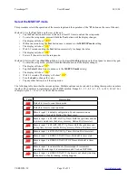
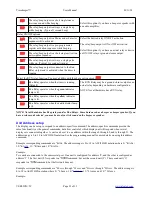
Страница 14: ... values depending on the state of the various inputs Display Value Description A Button 1 B Button 2 C Button 3 D Button 4 E Button 5 F Button 6 G Button 7 H Button 8 0 Remote Input 1 1 Remote Input 2 2 Remote Input 3 3 Remote Input 4 4 Rotary Encoder Knob or button A 5 Rotary Encoder Knob or button B 6 50Hz 60Hz Sync signal detected 7 32 768Hz Internal Oscillator detected Normal operation The dis...

Страница 15: ...f the warning times Pulsing beep until reset steady beep until reset and beeper disabled Press and hold the Mode button until the display changes Turn the Knob to select the desired beeper mode The following table describes the various options Multiple options can be selected by adding the respective numbers together Value Description bb00 Mode 0 Beeper off bb01 Mode 1 A single beep when the timer...

Страница 16: ...the timer is reset F02 Mode 2 Auto Restart mode In this mode the timer automatically restarts counting down from the preset value each time the timer reaches zero The Auto Restart mode works in both count up and count down modes The count up mode uses the count down timer preset time to determine when to reset the count up timer back to zero and restart F03 Mode 3 Change to count up when the timer...

Страница 17: ...re selects whether the count up timer display shows hours minutes seconds or fractions of a second Method 1 Use the Test button on the rear of the unit Tap the Test button on the rear of the unit at least 15 times to unlock the setup mode To enter the setup mode press and hold the Test button until the display changes The display will show uuu Wait 2 3 seconds and tap the Test button successively ...

Страница 18: ...S FF MM SS FF MM SS FF Hours Minutes Seconds 100ths u 9 HH MM SS HHH MM SS F H MM SS F M SS F Minutes Tens of Seconds u A HH MM SS HH HH MM SS HH MM SS MM SS Hours Minutes Seconds u b HH MM SS HH HHH MM S HHH MM S H MM S Hours Minutes Tens of Seconds u C HH HH MM HH HH HH MM HH HH MM HH MM Hours Minutes u d HH HH MM HH HH HHH M HH HHH M HHH M Hours Tens of Minutes u E HH HH HH HH HH HH HH HH HH HH...

Страница 19: ... other button to exit the setup mode The following table describes the various options Multiple options can be selected by adding the respective numbers together The numbers are represented in ASCII HEX notation Range 0 1 2 3 4 5 6 7 8 9 A B C D E F For example 8 plus 2 10 or A in ASCII HEX notation L Value Description L00 Default to timer to count down mode L01 Default to timer to count up mode L...

Страница 20: ...ly to change the value The display will show R01 Power off the unit to exit the setup mode Method 2 Units with Timer Start Stop button Use the timer Start Stop button on the front panel or remote keypad To enter the setup mode press and hold the Start button until the display changes The display will show FF Tap the Select button several times to advance to the beeper and relay setting The display...

Страница 21: ...tor lamp is lit r20 Run Relay operates when the yellow indicator lamp is lit r30 Run Relay operates when the red indicator lamp is lit NOTE Not all hardware has Beep relays and or Run Relays Some hardware has a beeper or beeper speaker If you have a relay mode selected you may hear only a click sound on the beeper or speaker Unit Address setup The display can be set up to respond to an address spe...

Страница 22: ...the general commands but allow control of which display unit will respond when several displays are connected together A unit can be set to one address within the range 0 through 9 and A through F The address range is 000 to FFF in ASCII HEX notation for a total of 4096 possible addresses Example corresponding commands are A000 through AFFF The address range is 000 to FFF in ASCII HEX notation See...

Страница 23: ... setting The display will show EE Wait 2 3 seconds The display will show E4 Turn the knob to change the value Tap any other button to exit the setup mode Time of Day Clock and serial data output setup Time of day clock and Serial data output setup Method 1 Use the Test button on the rear of the unit Tap the Test button on the rear of the unit at least 15 times to unlock the setup mode To enter the...

Страница 24: ...r L0 commands on the serial port C08 Default to remote mode C0A Remote Control Mode This mode is used to remotely control another timekeeper connected to this unit Pressing a button on this unit generates KPn commands that are sent to a remotely connected timekeeper The remote timekeeper sends RLY DSP or L0 responses to this unit C00 Send Lnxxxx commands on the serial port Where n is the unit addr...

Страница 25: ...he Test button on the rear of the unit at least 15 times to unlock the setup mode To enter the setup mode press and hold the Test button until the display changes The display will show uuu Within one second tap the Test button several times to advance to the default brightness setting The display will show YYY Wait 2 3 seconds and tap the Test button successively to change the value The display wi...

Страница 26: ...panel or remote keypad To enter the setup mode press and hold the Start button until the display changes The display will show FF Tap the Select button several times to advance to the default brightness setting The display will show 1 Wait 2 3 seconds The display will show 1 00 Turn the knob to change the value The setting Y09 is max brightness and Y00 is minimum brightness Tap any other button to...

Страница 27: ...contains information that might be useful for system designers system integrators and installers Power up When the unit is first powered up all the LEDs come on and the scrolling message Hello appears in the display NOTE If the Hello message appears but does not scroll the firmware is a variation not described by this manual NOTE If you have stored a power up preset the Hello message will not appe...

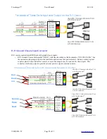
Страница 28: ... 6 BL 3 RD Use 6P6C Crossover Modular Cord Use 6P6C Standard Modular Cord with LED displays IN 3 12V IN 4 IN 1 Ground IN 2 RJ 14 Reset Pause Run Lap Timer Run Lap 12V Timer Pause Ground Timer Reset Timekeeper TM Remote Ground Closure Inputs Setup as a Counter with Timekeeper TM Display 1 WH 2 BK 4 GN 5 YL 6 BL 3 RD Use 6P6C Crossover Modular Cord Use 6P6C Standard Modular Cord with LED displays IN...

Страница 29: ...RX422 Jack will receive data on the Data 1 pair and transmit data on the DATA 2 pair The RJ45 connectors are configured as follows Pair 1 Blue White is used for RS422 data transmission reception Pairs 2 3 4 Orange White Green White and Brown White are used to carry 12VDC power In some cases Pair 2 Green White are used for data in the reverse direction These units have special configuration jumpers...

Страница 30: ...when the 12VAC50VA wall transformer is used Larger loads require a distribution module Each distribution module can drive up to a 9A load when the SYM04 power supply is used Beeper and or Relay Output See the specific relay output applications on how these optional configurations are used Run Relay Some models have an NPN ground closure output Specific models may be equipped with a relay with 2 5A...

Страница 31: ... is generating the sync signal This is not available on all models The clock LED flashes once every 2 seconds When the clock LED is making very short flashes one per second the internal 32KHz crystal is generating the SYNC signal In this mode the clock is the much more accurate In this mode the clock has an accuracy of 20 parts per million External 50hz sync has been detected The clock LED blinks ...

Страница 32: ...e DSP256B Revision G The B button is fixed to eliminate some erratic behavior that caused the timer value to increment For models with a rear panel Test button and a rear panel B button the B button starts the timer Pressing the B button while the timer is running momentarily freezes the display to show the lap time While in the timer mode the Test button becomes timer stop A new mode was added L0...

Страница 33: ... the beep mode BB03 the beep steady until reset mode was leaving the beeper always sounding Now the beeper clears after passing through this mode Version 54 Debug output was added that detects the IR remote by sending the command IR to the serial port Debug output was added that detects whether the 32KHz crystal is working by sending the command SYNC 32KHz to the serial port Version 56 Added suppo...

Отзывы: