Always
O
n UPS Systems
M0309_N_Series_ABS_700-3kVA_User_Manual V2.8 2012-06-12
27
12.3.
AS-400 and Relay Contact (Optional)
Located on the rear panel of the UPS is a connector, which provides status
information through relay and photo-coupler of the UPS operation.
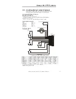
Pin Assignment (DB 25pin male connector)
Input signal pin assignment:
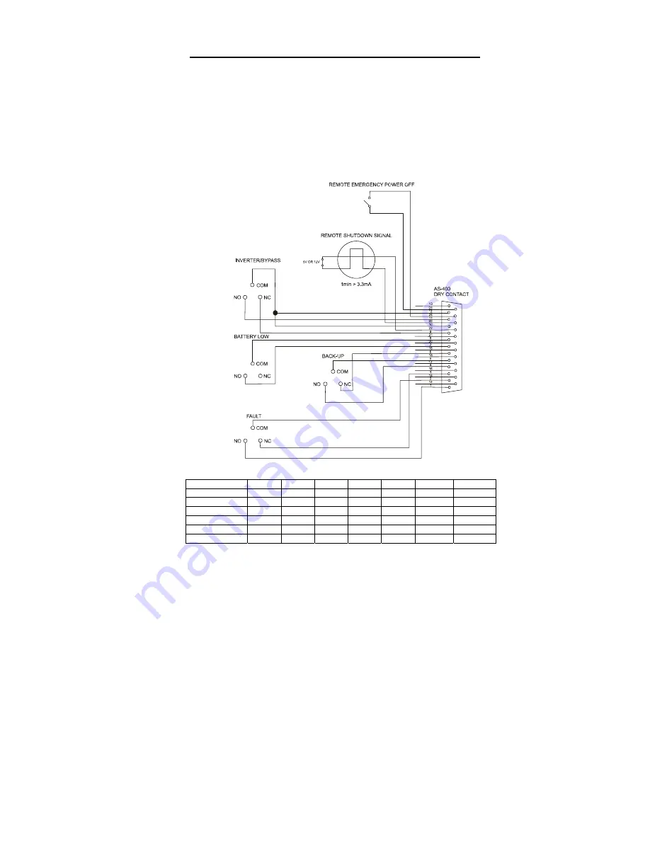
Remote Emergency Power Off: Pin 24, 25
When pin 24 and pin 25 are shorted, the UPS will power off immediately.
Remote Shut Down: Pin 22, 23
If V
pin22
> V
pin23
(5V~12V), the UPS will power off after 1 second.
Output signal pin assignment:
Fault
Pin 1, 2, 3
On Battery
Pin 4, 5, 6
Battery Low
Pin 7, 8
On Bypass
Pin 9, 10
On Inverter
Pin 11, 12
Dry Contact Capacity:
3A / 250VAC Max
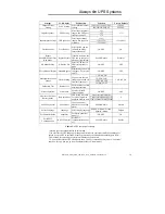
Figure 12.3.1
Line drawing of AS-400 Communications interface
*1 = Inactive. State may be “open” or “closed” condition
State
Pin 1,2
Pin 2,3
Pin 4,5
Pin 5,6
Pin 7,8
Pin 9,10
Pin 11,12
Normal
Open Closed
Open Closed
Open Open Closed
Fault Closed
Open
*1
*1
*1
Closed Open
On Battery
Open
Closed Closed Open
*1
Open Closed
Battery Low
Open
Closed Closed Open Closed Open
Closed
On Bypass
*1
*1
*1
*1
*1
Closed Open
On Inverter
Open
Closed
*1
*1
*1
Open Closed
Table 12.3.1
Output Truth Table

