ALTUS ClioAir Скачать руководство пользователя страница 25

       25 

ALTUS

  |  

3731 Northridge Dr, NW  

|

  Suite 1  

|

  Walker, MI 49544  

|

  T: 888.537.1311  

I

  www.altus-inc.com  | 


AS-1584_Rev.I

Troubleshooting

Technology W

orkstation Solutions — Powered

air

Cart will not power up:


• Plug power cord into a working hospital grade outlet. Note: Do not plug  


  into a multi-outlet surge distribution strip. 


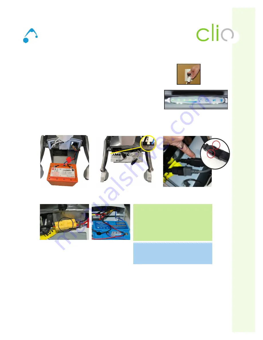
• Check to make sure power cord is plugged securely (See Fig. A). 


• Check to make sure the Power System is charging when plugged in (See Fig. B) 


  (Right four (4) Green LED lights will be flashing if charging).


• Check to make sure all cables to the power system are secure (See Fig. C).


the Blue (LiFe) RJ45 cable ends are secured/snapped into place. First end 


  location is in the LiFe Battery (see Fig. 1). Second end location is in the  


  power controller


• Make sure Power connection from the power controller is secure (Fig. D)


 Both the AC-In and AC-out connector ends include a locking feature (red tabs) to prevent from pulling apart. 


  To check the connections are secure, look at red tabs and  pull back and make sure they are locked into place. 


Note: Older models may not have this feature (red tabs) so simply disconnect.

Cart will not charge:


• Check to make sure external spiral cord secure within the cart. 


• Ensure outlet is functionally operational. 


• Plug power cord into a working hospital grade outlet. Note: Do not plug into a multi-outlet surge distribution strip. 


• Check and make sure the External User Interface (EUI) indicates the unit is charging when plugged in. 


• If charge level is low (last one or two LED lights lit) let charge until full.  


• If cart still does not charge, check to make sure all cables to the power system are secure.


• If cart still does not charge, resetting the controller is recommended (this is called a Hard Reset). To perform 


  a hard reset, disconnect the yellow battery terminals, wait for 10 seconds, then reconnect battery terminals. Make 


  sure both end “click” together. Note: The Hard Reset will remove all current from being fed into the controller and 


  will assist with a battery that remains in battery recovery mode.

(Fig. A)

(Fig. B)

Fig. C 

(LiFe Battery - Back side)

Fig. C 

(Power Controller- Front side)

Fig. D  

(Power Connection is Secure)

Fig. E 

(Battery terminals)

Fig. E 

(Battery terminals)

Located in back on 

Ascend EL

Cart will not power on or charge: Perform a 

voltage meter reading by taking a reading at 

the bat/- terminals and then again at  

the +/- terminals on the controller.
Normal reading: 10.5V-13.4V on a 12V battery

Abnormal reading: 13.4V and below 10.5V

Actuator is connected directly to the battery. If 

battery is dead, the actuator will not work. 

When plugged in, the cart will charge first then 

be able to service the actuator.

(Fig.1)

Содержание ClioAir

Страница 1: ...Technology Workstation Solutions Powered Service Manual air November 2020 ...

Страница 2: ... Unit 9 Power System Overview 10 11 Battery Power System Removal Installation 12 14 Circuit Breaker Overview 15 Basic Troubleshooting 16 25 air Software Installation Note Make sure your cart workstation USB port is connected to the USB port on the MPM Power unit controller installed in your cart Download the Powervar MPM View install package and save it to the workstation desktop or other convenie...

Страница 3: ...s or across walls or floors Fully insert certified detachable spiral cord plug into outlet DO NOT unplug by pulling on cord For 250VA models a type not lighter than SJT 18AWG should be used DO NOT remove bend or modify any metal prongs or pins of spiral card cord DO NOT use excessive force to make connections Keep spiral cord away from water DO NOT PLUG CORD INTO OUTLET IF WET Keep children away f...

Страница 4: ... Lever 4 Handle 5 Large Thermofoil Worksurface Area 6 Keyboard Platform 7 Mousing Area 8 LCD Monitor Support 9 User Interface 10 Power System Battery Compartment 11 Internal Technology Cable Management 12 3 Outlet Power Cord not shown 13 Coiled Power Cord Holder 14 Battery Access Panel back 15 Up Down Button electric lift only 7 9 14 6 4 3 4 5 2 1 Technology Workstation Solutions Powered air 12 13...

Страница 5: ...d Platform Adjustment Instructions Technology Workstation Solutions Powered air The keyboard platform is tilted and stored at 90 degrees for shipping purposes only See Fig A To use Place both hands on each side of the keyboard platform and simply tilt to desired position and slide out for use See Fig B 1 2 A B ...

Страница 6: ...board platform and mouse tray are equipped with wire managers to keep wires in place See Fig A Keyboard and Mouse Wire Management to inside of technology storage area Feed both keyboard and mouse wires through access hole located under the handle See Fig B Inside of technology storage area Once cables are through hole pull through See Fig C Auxiliary holes See Fig C 1 2 Keyboard and Mouse Wire Man...

Страница 7: ... work surface assembly Attach 2 5 16 18 Flange Hex Nuts to bolts underneath the rear work surface assembly Tighten with 1 2 wrench preferred or dis posable 1 2 wrench included To manage cables within the Monitor Sup port remove cover from back of support Use a 2 Phillips Screwdriver to remove back cover Do not discard 4 8 x 5 8 screws 1 2 Internal Cable Management Flat Screen Monitor Support Clio ...

Страница 8: ...of screw by the depth of mounting location on back of monitor If too long of screw is used damage to monitor may occur Managing monitor cables Once monitor is attached Adjust monitor to its highest position Manage cables from monitor down and through cable management hole Reinstall back cover Make sure to route the cables through the side access holes in cable management cover Reinstall 4 screws 6...

Страница 9: ...wer system will beep and the far left LED light will turn on At this point all powered devices connected to the outlet strip should receive power Once on the LED Keyboard light may be used Press to turn light on off The LED Keyboard light has a 5 minute timeout function just in case the light was not turned off by the operator Note Monitors laptops and other devices will need to be manually turned...

Страница 10: ...g On System Turning Off System Mute Button Use Press and hold power button for approximately 3 seconds Press and hold power button for approximately 3 seconds Press and hold until audible alarm discontinues Fuel Gauge Power System will beep The LED on the left side turns green All components will receive power Fuel Gauge Power System will beep LED on left side will turn off If Power System is plug...

Страница 11: ...0 charged Component should still be plugged in when possible to maximize battery life Flashing Green Each LED flashing green reflects the level of charge achieved during recharging No Light Power System is turned off or battery is not properly connected to the power system LED Position 5 Charging Status when plugged into wall outlet Solid Green Battery is full Battery Low LED 2 Flashing Yellow ON ...

Страница 12: ...Off Button for 2 seconds Step 2 Long term Storage more than 2 months Warning If cart will not be used for more than 2 months turn off the cart by holding the ON OFF Button The battery will need to be recharged every 30 days to prevent damage Step 3 Remove back access panel by loosening and removing 2 screws See Fig A Step 4 Remove back panel Remove strap and slide battery from base See Fig B Step ...

Страница 13: ...cement Technology Workstation Solutions Powered air Battery Removal Continued Step 7 Disconnect blue RJ45 cable from controller See Fig E If replacing with a SLA battery this step is not necessary Step 8 Replace with new battery and repeat Steps 1 7 in reverse order Make sure all connections are fully seated Blue RJ45 Cable Fig E ...

Страница 14: ... only if using the MPM Software If the MPM Software is not used proceed to step 2 Connect the USB cable into the technology component within the cart or into a resident laptop with the MPM software loaded 2 Wait for the double yellow to appear on the interface 3 When this happens press and hold the mute button for 5 seconds One beep will be made immediately Within 3 5 seconds after the initial bee...

Страница 15: ...to protect themselves from any current spikes found within the system These spikes would only happen in extreme cases and the breaker can eas ily be reset in seconds A user would be able to tell that the circuit has been tripped if the cart will no longer raise or lower The user can reach under neath the right side of the cart and press the button in to reset the circuit This will return the cart ...

Страница 16: ...16 ALTUS 3731 Northridge Dr NW Suite 1 Walker MI 49544 T 888 537 1311 I www altus inc com AS 1584_Rev I Troubleshooting Technology Workstation Solutions Powered air ...

Страница 17: ...17 ALTUS 3731 Northridge Dr NW Suite 1 Walker MI 49544 T 888 537 1311 I www altus inc com AS 1584_Rev I Troubleshooting air Technology Workstation Solutions Powered ...

Страница 18: ...18 ALTUS 3731 Northridge Dr NW Suite 1 Walker MI 49544 T 888 537 1311 I www altus inc com AS 1584_Rev I Troubleshooting Technology Workstation Solutions Powered air ...

Страница 19: ...19 ALTUS 3731 Northridge Dr NW Suite 1 Walker MI 49544 T 888 537 1311 I www altus inc com AS 1584_Rev I Troubleshooting Technology Workstation Solutions Powered air ...

Страница 20: ...2o ALTUS 3731 Northridge Dr NW Suite 1 Walker MI 49544 T 888 537 1311 I www altus inc com AS 1584_Rev I Troubleshooting Technology Workstation Solutions Powered air ...

Страница 21: ...21 ALTUS 3731 Northridge Dr NW Suite 1 Walker MI 49544 T 888 537 1311 I www altus inc com AS 1584_Rev I Troubleshooting Technology Workstation Solutions Powered air ...

Страница 22: ...22 ALTUS 3731 Northridge Dr NW Suite 1 Walker MI 49544 T 888 537 1311 I www altus inc com AS 1584_Rev I Troubleshooting Technology Workstation Solutions Powered air ...

Страница 23: ...23 ALTUS 3731 Northridge Dr NW Suite 1 Walker MI 49544 T 888 537 1311 I www altus inc com AS 1584_Rev I Troubleshooting Technology Workstation Solutions Powered air ...

Страница 24: ...Step 4 Remove controller from base Phillips Head Screwdriver needed A Loosen and remove 2 screws See Fig B B For Ascend EL Carts slide out controller See Fig B Step 5 Gently slide controller out of base Step 6 Disconnect Cables 6 from Power System A Unplug Black and Grey CAT 5 cables from unit See Fig C B Unplug Blue CAT 5 Smart Battery Cable from unit See Fig C B Unplug USB cable from unit See Fi...

Страница 25: ... operational Plug power cord into a working hospital grade outlet Note Do not plug into a multi outlet surge distribution strip Check and make sure the External User Interface EUI indicates the unit is charging when plugged in If charge level is low last one or two LED lights lit let charge until full If cart still does not charge check to make sure all cables to the power system are secure If car...

Отзывы: