8
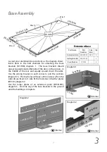
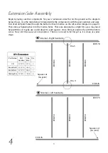
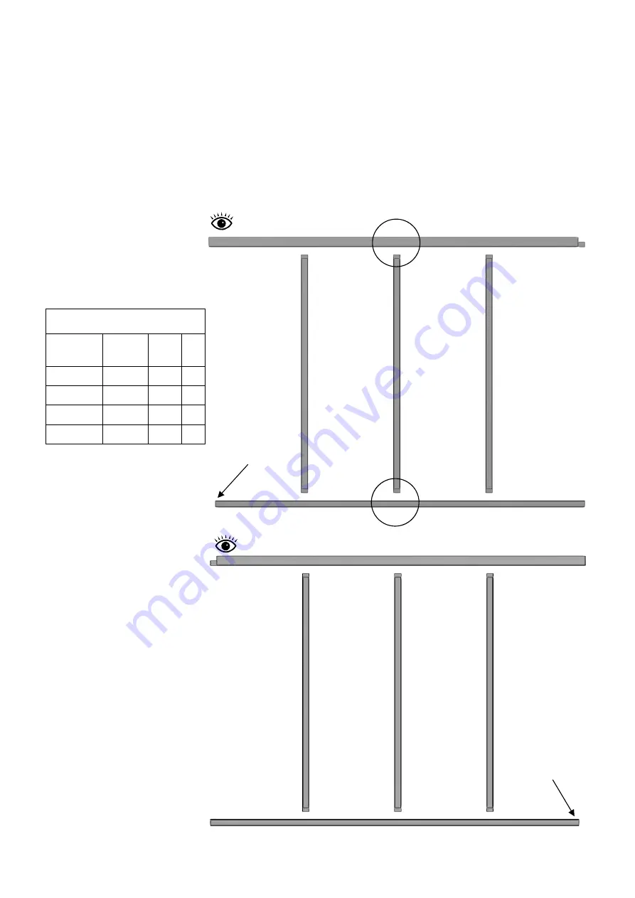
Begin by laying out the components for your 2 extension sides flat on the ground as the diagram
below shows. Use the table below to help identify the components with the part numbers and sizes.
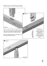
First of all drill pilot holes through the bottom of each mortise on the cill section (diagram 4, page 9).
Then slot each glazing bar into the mortise holes. These are designed as a tight fit so you may need
help with this or maybe use a solid object to push against. Once firmly in position fix with the 50mm
screw. Now slot the eaves rail into position. There is no need to fix this yet as it is done at a later
stage.
Extension Side Assembly
4
Part
Number
Size
(mm)
Qty
EV0176 2476 2
EV0179 2564 1
EV0030 1588 6
8ft Extension
Part Name
Cill
Eaves Bar L
Glazing Bar
Eaves Bar R
EV0178 2564 1
EV0030
EV0179
EV0176
EV0030
EV0030
Internal – Left hand side
Square cut
(no joint)
EV0176
EV0178
EV0030
Dia. 4
Dia. 5
Internal – Right hand side
EV0030
EV0030
Square cut
(no joint)
Содержание Evolution 10
Страница 1: ...11 14 Standard building Extension...
Страница 26: ...26 Notes...
Страница 27: ...27 Notes...


