background image

17 


Rear Assembly


EV

00

12


EV0063 

Pilot hole 

50mm 

Diagram 18 

Internal 

EV0061 

EV0062 

EV0012 

Dia. 18 

Pilot 
hole 
here 

Internal 

NB 

there 

are 

no 

mortise 

holes on 

these 

gable bars. 

EV0075 

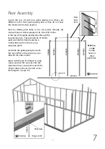
Locate the rear cill and rear gable glazing bars (these are 
different to the front gable glazing bars as they do not have 
the mortise for the door header).  
 
Start by drilling pilot holes in the cill section through the 
mortise holes as before (diagram 18).  Also drill 2 holes  
in the top of the gable glazing bars through the  
lap joint location.  These should be 25-30mm  
apart and the first hole should be a  
similar distance from the very top  
edge (see right)  
 
Assemble the gable glazing bars with  
the rear cill flat on the ground as you  
did with the side sections.   
 
Again with the aid of a helper or using  
a prop position the rear end onto the  
aluminium base.  Locate the end of the  
cill into the mortise on the side corner  
bar (diagram 7, page 10). 

30mm 

30mm 

EV0063 

EV0060 

Содержание Evolution 10

Страница 1: ...11 14 Standard building Extension...

Страница 2: ...ructions Contents Introduction Base Preparation Overview Base Assembly Side Assembly Front Assembly Extension Installation Rear Assembly A frame Assembly Roof Assembly Section 1 2 3 4 5 6 7 8 9 Page 3...

Страница 3: ...ther vulnerable locations To minimise the risk of wind damage try to select as sheltered a site as possible e g beside a hedgerow or garden fence Additional Considerations Please bear in mind that ass...

Страница 4: ...o and convenient to bring water to and possibly a supply of electricity Finally and most importantly choose a site where your Alton Greenhouse will look right so that it will complement your garden Ba...

Страница 5: ...g through one piece of timber into another it is always recommended to predrill the first piece This will prevent the timber from splitting which could weaken the structure You can build the sides of...

Страница 6: ...ning on a set of steps All you have left to do now is fit the gutter and downpipes think about where you might site a waterbutt when doing this You can always add a Partition or another Extension at a...

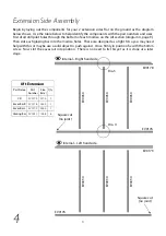
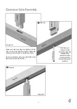
Страница 7: ...holes will take a 25mm screw when the side cills are fixed to it Also fit the front door cill with 2 plates HE512 diagram 2 Use the larger plates at an extension point EV0312M diagram 3 Don t fix any...

Страница 8: ...ht fit so you may need help with this or maybe use a solid object to push against Once firmly in position fix with the 50mm screw Now slot the eaves rail into position There is no need to fix this yet...

Страница 9: ...ll the way in you may find they need a light tap with a wooden mallet or something similar If you are going to glue your joints this is the first point you would do this 50mm Screw Pilot hole it is ea...

Страница 10: ...ch other so the screws don t intersect each other Now offer the side corner to the eaves bar slotting the tennon into the mortise shown in diagram 5 do not fix this joint as it will be done at a later...

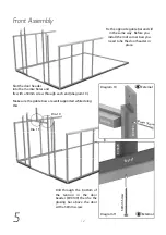
Страница 11: ...tennon of the front cill into the side corner bar as before diagram 9 Fix this with a 80mm screw Also screw this to the base with 25mm screws Keep the gable glazing bar supported while you get the ne...

Страница 12: ...nal Drill through the bottom of the tennon in the door header EV0109 then fix the glazing bar above the door with a 50mm screw 50mm Screw EV0109 EV0078 Diagram 10 EV0070 EV0109 50mm Screw External Dia...

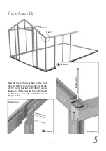
Страница 13: ...ars to the front end As before fix the lap joint at the top of the gable bar first with 40mm screws diagram 17 then secure the bottom end to the eaves bar with a 80mm screws diagram 18 Diagram 12 Inte...

Страница 14: ...aluminium base and slide it up to the forst side section until the tenon slots into the mortise joint With help or the aid of a prop screw the cill to the base using 25mm screws Diagram 14 Diagram 15...

Страница 15: ...cill Slot the top into position lining the edge of the bar up with the joint of the two eaves bars Secure this with a 50mm screw and the secure the bottom with a 40mm screw remember to drill a pilot h...

Страница 16: ...s Don t fix the top of the bar until the roof corner bars have been fitted Part Number Size mm Qty EV0012 3106 1 EV0042 1794 1 EV0043 1794 1 10ft Rear Part Name Cill Roof Corner R Roof Corner L Side C...

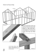
Страница 17: ...he cill section through the mortise holes as before diagram 18 Also drill 2 holes in the top of the gable glazing bars through the lap joint location These should be 25 30mm apart and the first hole s...

Страница 18: ...lazing bars diagram 19 Now fix the roof corner bar and side corner bar through the eaves bar with an 80mm screw You can then screw the base to this section with a 25mm screw EV0061 EV0043 40mm Screw E...

Страница 19: ...me next Take the eaves extension braces and locate them in the mortise slots in the extension side bars Pilot hole and fix these with 40mm screws Make sure the flat face that meets the side bar is sea...

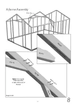
Страница 20: ...am 22 Before fixing these it would be a good idea to fit the A frame brace diagram 24 Once these are all in place check they are all inserted correctly and fix them with 40mm screws Dia 22 Dia 23 Don...

Страница 21: ...21 A frame Assembly 8 Diagram 24 Dia 24 EV0188 40m m Screw 40m m Screw E V 0 1 8 1 EV0191 EV0191 EV0188 Note For a neater finish insert the screws in the rear of the bar...

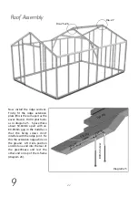
Страница 22: ...ce these about 50 60mm apart with an 80 90mm gap in the middle so that the fixing screws don t interfere with the ridge joint Fix this the extension ridge while on the ground Lift it into position and...

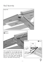
Страница 23: ...through the top face of the roof corner bars This is to prevent the end or the screw coming through the bottom of the roof glazing bar This angle will also give a much better and stronger fixing Diag...

Страница 24: ...e main ridge section locate this with the roof corner bars on the front of the building Fix this as before and then fix the ridge plate to the main ridge as shown in diagram 25 with 80mm screws Dia 29...

Страница 25: ...25 Roof Assembly 9 Now the ridge bars are installed you can return to section 7 on page 19 of your main book to complete the assembly of the building...

Страница 26: ...26 Notes...

Страница 27: ...27 Notes...

Страница 28: ...Alton Greenhouses TGP Ltd Blythe Park Cresswell Stoke on Trent ST11 9RD Telephone 01782 385 409 www Altongreenhouses co uk sales altongreenhouses co uk...

Отзывы: