MOD-16P
Instruments:
1. signal generator: 8903b
2. oscillograph: LS8106
3. modulator: JMM-2200
4: frequency recorder: EFC-3203A
5. DC power supplier: 3303A.
6. multi-meter
7. frequency spectrum: E4403B
Instruments Setting:
1. signal generator: 1kHz/65mV.
2. modulator:
2.1. Tone set: H: Pass: 3K L: Pass: 50K RANGE: 10
2.2. AF set: H: Pass: 25 L: Pass: 15K RANGE: 50
Test procedure and specification:
1. Turn on the power supply (press the ON/OFF key for 2 seconds), the LED indicator
will light up, after the LCD show the battery and frequency status, the bright of LED
indicator will be decreased.
2. Test the sense power of PL2 on CH0, CH50, CH99 are above 5dBm, the sense
power of PL1 is above 2dBm, the sense power of PL0 is above -4.5dBm, and the
harmonics is below -45dBm. (Note: the power of PL1/PL2/PL0 must have obvious
variation)
3. Input signal from MIC input terminal (shout), the modulator will have output.
4. Tone test: Tone signal is in the range of 3KHZ±0.5KHZ, the frequency is in
31~34KHZ.
5. In standard range test the radio frequency, and permit the error in
±2KHZ.
- 18 -
Содержание MOD-16H Series
Страница 1: ...MODEL MOD16H 16P ...
Страница 13: ...PCB UP MIC Top Layer Top Overlay Top Solder PCB UP MIC Bottom Layer Bottom Solder 6 PCB LAYOUT MOD 16H 11 ...
Страница 15: ...PCB UP 8P A Bottom Layer Bottom Overlay Bottom Solder PCB UP 8P A Top Layer Top Overlay Top Solder MOD 16P 13 ...
Страница 17: ...PCB UP 8P MIC Bottom Layer Bottom Solder PCB UP 8P MIC Top Layer Top Solder 15 ...
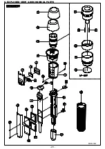
Страница 22: ...8 EXPLODED VIEW MECHANICAL PARTS MOD 16H 20 ...
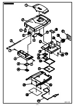
Страница 23: ...MDO 16P 21 ...


