background image

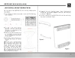
DEVICE WALL MOUNT INSTRUCTIONS

2

Label

Millimeters 

(mm)

A

7.2 +/- 0.5

B

2.6 +/- 0.15

C

19.0 +/- 1.2

D

3~4

UBC1319AA00 Quick Installation Guide

5.

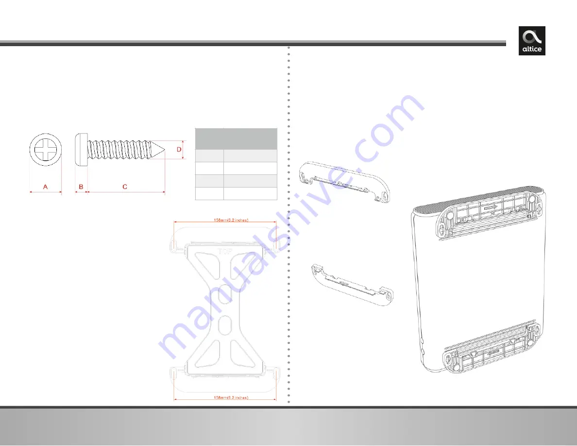
Separate  the  wall  mounting  pieces.  Mount  the  top  and 
bottom  leg  stand  pieces  (

Figure  1

)  onto  the  UBC1319AA00 

as shown in 

Figure 2

6.

You  can  now  mount  the  UBC1319AA00  onto  the  wall  using 
the screws installed in Step 4.

2.

Fit  the  2  leg  stand  pieces 
together  with  the  wall  mount 
template  as  represented  in  the 
graphic to the right.  

3.

Place this on the wall and use it 
as  a  template  to  mark  the  wall 
for  the  appropriate  placement 
of the screws. 

4.

Install  the  2  sets  of  screws  on 
the  wall  (158  mm  or  6.2  inches 
apart). 

NOTE: 

The screws should protrude 

from  the  wall  so  you  can  fit  the 
device  between  the  head  of  the 
screws  and  the  wall.  If  you  install 
the  screws  in  drywall,  use  hollow 
wall  anchors  to  ensure  the  unit 
does  not  pull  away  from  the  wall 
due  to  prolonged  strain  from  the 
cable and power connectors.

You  can  mount  the  UBC1319AA00  on  a  wall  by  following  the 
steps below: 

1.

You will need 4 round or pan head screws with the following 
measurements:

Figure 1

Figure 2

Содержание UBC1319AA00

Страница 1: ...UBC1319AA00 DOCSIS 3 0 Wireless eMTA Quick Installation Guide ...

Страница 2: ...the same wall outlet you must use a cable line splitter not included 2 Connect an Ethernet cable supplied to one of the ETH Ethernet port on the back panel of the modem and connect the other end to the Ethernet port of a computer Use a Category 5e or Category 6 Ethernet cable with RJ 45 connectors to ensure Gigabit Ethernet speeds when the computer supports it 3 Connect an RJ 11 phone cable not su...

Страница 3: ...to the right 3 Place this on the wall and use it as a template to mark the wall for the appropriate placement of the screws 4 Install the 2 sets of screws on the wall 158 mm or 6 2 inches apart NOTE The screws should protrude from the wall so you can fit the device between the head of the screws and the wall If you install the screws in drywall use hollow wall anchors to ensure the unit does not p...

Страница 4: ...e modem to automatically turn off the LEDs in order to conserve energy Note that the POWER LED will remain lit in ECO Mode When pushed the INFO button will disable the LED ECO Mode for 30 seconds and the LEDs will operate in the Normal State as seen in the LED table on page 4 When the modem is in a faulty or alarm condition LED ECO Mode is automatically disabled When the condition is resolved the d...

Страница 5: ...S button is pushed otherwise will be OFF OFF N A WIFI On Solid White WiFi Enabled OFF WiFi Disabled OFF Blinks White WiFi initialization issue PHONE On Solid White eMTA Registered Successfully OFF eMTA Disabled OFF Blinks White eMTA registration failed POWER ON Solid White ON Solid White N A but will remain ON if power connected REAR PANEL TEL ON Solid Green Telephone is connected Blinks Green Tel...

Страница 6: ...paration between the equipment and receiver Connect the equipment into an outlet on a circuit different from that to which the receiver is connected Consult the dealer or an experienced radio TV technician for help 5 UBC1319AA00 Quick Installation Guide 5GHz Wireless Statement For operation within the 5 15 5 25GHz and 5 47 5 725GHz frequency ranges this device is restricted to indoor environments T...

Отзывы: