Instruction manual 91/104 V9.2
Commissioning
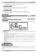
Set the proportional gain of the speed loop: the larger the number is, the faster the motor is in response, but the instability of the regu -
lator is at risk. For the adjustment of this parameter it is recommended to start from a low number (2.0, 3.0) and then, after enabling
the motor and rotating it, gradually increase it until it is possible without making the system unstable.
NOTE:
To
select the gain in use (Gain 1 or Gain 2) the digital input to "
Gain Selection
“ is used; the Gain 1 is used if the input
that controls the switching of the gain is at level 0, instead the Gain 2 is used if it is level 1. The digital input that controls
switching is set in the “Dig.Inp. X Dest“ menu (see page 43); u nder standard conditions this input is the DI3
.
Speed loop int. 1 / 2
Minimum Maximum Units of measure
0
999,99
-
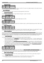
Set the additional gain of the speed loop: the larger the number, the more the motor quickly resets the speed error (difference between
the required speed and the actual speed), but the instability of the regulator is at risk. For the adjustment of this parameter it is recom-
mended to start from a low number (0.01, 0.02) and then, after enabling the motor and rotating it, gradually increase it until it is pos -
sible without making the system unstable.
NOTE:
To
select the gain in use (Gain 1 or Gain 2) the digital input to "
Gain Selection
“ is used; the Gain 1 is used if the input
that controls the switching of the gain is at level 0, instead the Gain 2 is used if it is level 1. The digital input that controls
switching is set in the "Dig.Inp. X Dest“ menu (see page 43); under standard conditions this input is the DI3.
Speed loop gain scale
Minimu
m
Maximu
m
Units of
measure
0,1
99,9
%
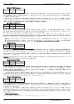
This parameter is displayed only in “Async.HighSpd" mode (see parameter "Motor Type“ on page 35), and is used to scale the addi-
tional gain of the speed loop when the motor runs at a frequency above the rated one (parameter "Nominal Frequency“ on page 36).
When the inverter is set to “Async.HighSpd " mode and the motor is running at high speed if you notice a speed instability (pecking
after a change) then you have to reduce this value. Conversely, if you want more accuracy of response and the motor can respond
well, you can increase the value.
Example:
If this parameter is set to 10 % it means that at high speed the additional component (parameter " Speed loop int. 1 / 2”) will
have a value of 10 % compared to the number set in its parameter.
An.Inp.1 Gain 1
Minimum Maximum Units of measure
-2.00
+2.00
-
Set the multiplication factor of the signal coming from the analog input 1. With this parameter it is possible to scale the voltage signal
connected to the analog input in order to adapt it to reach the maximum speed. This gain parameter is active when the digital input
dedicated to switching the gain of AI1 is logically “0". Under standard conditions this input is the DI3; For more information see
paragraph "Dig.Inp. X Dest“ on page 43.
Example:
suppose we want to reach a maximum speed of 3000 RPM when the speed signal connected to the analog input 1 is at its
maximum value; unfortunately, the speed signal coming from the CNC has a full scale of 8.5 Vcc. You can calculate the scale value to
amplify it and thus get the maximum speed with 8.5V instead of 10V:
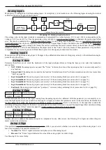
Gain
=
10
V
MAX
V
MAX=
Maximum voltage of the speed reference.
Gain = Gain of the analog input.
Substituting in the formula the bottom scale value of the example (8,5V) is calculated that the gain to be set in this parameter is 1.17.
An.Inp.1 Gain 2
Minimum Maximum Units of measure
-2.00
+2.00
-
The function of this parameter is identical to that described in the previous paragraph; The only difference is that this gain parameter
is active when the digital input dedicated to switching the gain of AI1 is logically “1 ". Under standard conditions this input is the
DI3; For more information see paragraph "Dig.Inp. X Dest“ on page 43.
An.Inp.1 Offset
Minimum Maximum Units of measure
-10.00
+10.00
%
Set the offset of the analog signal 1. For the adjustment of this parameter it is recommended to give a speed reference “0 " and then to
enable the drive; if the motor rotates slowly, act on this parameter to stop the rotation.
Alter Elettronica s.r.l.
39


