21
Altech VR Mini, VR1, VR2, VR3
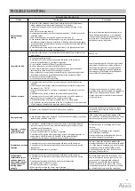
Problem
Checkpoints
Description
Heat exchanger
leaking
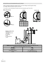
• Assembly of the exchanger connections with two wrenches (adjustment),
which safeguards against internal twisting of the collectors.
• Check if the leakage may be associated with mechanical damage to the
exchanger.
• Vent valve or drain plug leaking.
• Heating agent parameters (pressure and temperature) – should not exceed
permitted values.
• Type of heating agent (it cannot be aggressive to Al and Cu).
• Circumstances when the leakage appears (e.g. during the first, tentative
installation start-up, when the installation is filled up after the heating agent
has been drained) and outside temperature at the time of failure (risk that the
exchanger may freeze).
• Possibility of operating in aggressive conditions (e.g. high concentration of
ammonia in the air in a sewage-treatment plant).
Pay special attention that the exchanger may
freeze during winter time. 99 % of registered
leakages appear during installation start-up/
pressure tests. The defect can be removed by
pulling back vent or drain valve.
Fan works too loud
• Assembly of the device is in conformity with this manual (e.g. distance from
wall/ceiling).
Min. 40 cm
• Device appropriately leveled.
• Correctness of electric connections and qualifications of the wireman.
• Inlet current parameters (e.g. voltage, frequency).
• Use of rotation controller different from Altech regulators.
• Noise at lower gears (possible controller failure).
• Noise only at higher gears (regular situation explained by aerodynamic
characteristics of the device, if there outlet air chokes).
• Type of other devices operating in the building (e.g. induced draught fans) –
intensified noise caused by simultaneous operation of many machines.
• Does the fan rub against the casing.
• Is the fan evenly screwed to the casing.
Level of operating noise of devices is perceived
subjectively. If the device is made of plastic, it
should operate quietly.It is recommended to
unscrew the clamping screws and tightening
them up again. If the fault does not disappear,
contact Altech Technical Support.
Fan does not work
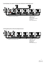
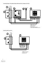
• Correctness and quality of electric connections and qualifications of the
wireman.
• Is there an additional bridge between required engine terminals (diagram in
the manual) – U1 – TK (TB).
• Inlet current parameters (e.g. voltage, frequency) on the clamp block of fan
engine.
• Correctness of operation of other devices installed in the building.
• Correctness of wire connections on the engine side acc. to the manual, in
comparison to wires clamped in the engine terminal strip.
• PE conductor voltage (if present, may mean there is a break-down).
• Is N conductor correctly connected to the fan or regulator, or is the connection
of U2 clamps on the motor and regulator made correctly.
Electrical connection need to be done strictly
according to the electric diagrams in the manual.
If there is no bridge between U1 and TK(TB)
clamps, the motor lacks thermal protection and
may break – burn.
• Damage or installation of controller different from regulator.
It is recommended to check the device/ speed
controller by connecting the heater directly to
power supply.
Damaged casing
• Circumstances when it was damaged – notes on the bill of ladings, stock issue
confirmation, condition of the box.
If the casing is damaged, make photos of the
box and device, confirming that the device serial
number on the device and on the box are the
same.
Regulator – rotation
controller does not
work/ it is burned
• Correctness – quality of electric connections (wires accurately positioned
in electric clamps, cross-section and the material wires are made of) and
qualifications of the wireman.
• Only 1 controller connected to 1 device.
• Inlet current parameters (e.g. voltage, frequency).
• Correctness of operation after connecting “in short” (skipping regulator, i.e.
connections L and TB, N and U2, PE and PE) to the power network.
• Check that the knob wasn't damaged during installation or use.
For the controller, the following must also be
checked:
•circuit breaker
•correctness of connection to the controller
•use of shielded conductors
•control conductors, which should be located
away from the working conductors
Actuator does not open
the valve
• Correctness of electric connections and qualifications of the wireman.
• Correctness of the thermostat operation (characteristic tick sound during
changeover).
• Inlet current parameters (e.g. voltage).
The most important is to check whether the
actuator responded to the electric impulse within
11 s. If the motor is damaged, you need to switch
actuator operation to manual (MAN), which
mechanically opens the valve. If the motor is
damaged, change actuator.
Programmable
thermostat does not
send any signals to
the actuator/ controls
the operation of the
heating system
wrongly
• Correctness of electric connections and qualifications of the wireman.
• Correctness of the thermostat operation (characteristic tick sound during
switchover).
• Connecting a few motor of devices directly to the thermostat
(permitted only if contactor is used).
• Inlet current parameters (e.g. voltage).
• When was the last time the sensor was calibrated.
• The thermostat is incorrectly connected directly to the motor.
RDE thermostat is powered by batteries, that
need to be replaced (every 2 years). Also, the
sensor needs to be periodically calibrated.
Warranty is not valid if the thermostat was
directly connected to the motor. If the sensor
incorrectly measures the temperature, it should
be calibrated (instructions in the catalogue).
TROUBLE SHOOTING
Содержание VR Mini
Страница 1: ...Heating unit Fl ktluftv rmare VR Mini VR1 VR2 VR3 1 12 Check us on EN Manual SV Manual...
Страница 24: ...24 Notes...
Страница 46: ...46 Anteckningar...
Страница 47: ...47 Anteckningar...


